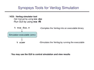
Synopsys Custom Designer Tutorial for a chip integration using
Synopsys Custom Designer Tutorial for a chip integration using the University of Utah Standard Cell Libraries In ON Semiconductor 0.5u C5 CMOS Version 3.0. Overview This tutorial will take you through the following steps:


Synopsys Custom Designer Tutorial for a chip integration using
E N D
Presentation Transcript
Synopsys Custom Designer Tutorial for a chip integration using the University of Utah Standard Cell Libraries In ON Semiconductor 0.5u C5 CMOS Version 3.0
Overview This tutorial will take you through the following steps: 1) import your GDS file from IC Compiler – referred to as the “core” - into a new library in Custom Designer. 2) add pins to the core for connectivity 3) add standard cells to the new library 4) copy a pad_frame_28 into the library as a template for the top-level chip 5) instantiate the core into the top-level chip 6) wire the core and pad frame together in layout and schematic 6) run LVS on the chip 7) run DRC on the chip 8) generate a chip level GDS to be sent to MOSIS for fabrication
Start the tool Create a working directory. Add cds.lib, lib.def and color map files into the working directory. Invoke the tool with “cdesigner &” Open the library manager and create a new library. Open the technology manager and attach the correct technology library to your working library.
Import GDS – step 1 • From Custom Designer Console we can import GDS. • From the Console, choose File > Import > Stream. • Under the Main tab, • specify required input details: Run Directory; Input GDS Stream file and top cell. • Output details: Output Library, view: Layout • Under the Options tab, specify optional details. • Under the Map Files tab, specify optional map file details. See the attached map file • Click OK.
Import GDS – step 2 Select the correct layer map.
Import Verilog to create Symbol for the Core in Custom Designer • From Custom Designer Console • Go to File Import Text Select this option to import Verilog to symbol & schematic
Import Verilog: Choose Input Netlist File and Target Library Select the language as Verilog Browse for your netlist file. However, all that is necessary is the port list to create a symbol. Choose the Target Library
Import Verilog: generate symbols and schematics views Choose Options tab Check this option to create a symbol
Fill your user’s library Copy all cells from the UofU_Digital_v1_2 library into your new library using Library Manager. Right click on the cells to copy. Also copy the Pad_Ring_28 cells into your library but rename it “final_chip”.
Fix your core ports The GDS import will have included text for the pins of your core but pins must be instantiated to tell LVS where connections in layout will be made.
Edit your chip layout Use “i” (or edit->add instance) to create an instance. Select the your core.
Layout hints Press “z” and draw a rectangle to zoom to area Press “shift f” to see internals of lower level cells. Press “control f” to hide internals of lower level cells. Press “f” to fit the view. Press “control r” to redraw after changing selection and visibility of layers. When “creating interconnect”, start with “p” and use Ctrl-V and Shift-V to switch metal layers through a via up or down, respectively. Press “q” to see the properties of an object.
Add connections to layout “Create Interconnect” to add wires to make IO connections, shift-v and ctrl-v to switch metal layers through a via as you migrate from one pin to the other.
Add all connections to layout Each IO has an “enable” which should be tied to ground (inputs) or vdd (outputs) If IO is an output, tie the “DataOutput signal to the appropriate pin on your core. Let the two “DataInput” signals float. If IO is an input, tie the “DataInput” signal to the appropriate pin on your core. Tie the “DataOutput” pin to ground. “DataInputN” can float. On all four sides we need to connect the power ring of the IO to the power ring of the core. We need similar connections between the ground rings as well.
Add connections to layout – Input Example Here a IO is configured as an Input. The input out signal is on the top right and the bottom shows the enable being grounded. DataInputN, Output of IO metal 2 DataInput, Output of IO metal 2, used when enable is tied low as in this case. DataOutput, input to IO metal 2, used when enable is high Enable, input to IO metal 2, tie high for Output Tie low for Input.
Add connections to layout – Example Output Here the enable is brought by metal 3 to the Vdd ring and the dataout signal is connected in metal 2.
Add connections to layout – Connecting the ground rings Use a thick metal 2 line between ground in a IO fill cell to the inner ring of your core to connect ground. Do this on all four sides.
Edit your chip Schematic In your chip level schematic view, you will see the 28 pin pad frame. You need to instantiate you core in the middle and connect to the padframe. Add wires to connect the two and add pins for the pads to go to the outside world. “I” will bring up the instantiation window and “w” will start to draw wires. The connections in the schematic should match the layout for LVS later. Save and check the design in the end.
Export Final GDS to be Fabricated • To export design data in GSDII format: • From the Console, choose File > Export > Stream. • In Main tab • Specify the output: Enter Run Directory and GDS file in Stream file name. • Specify the input: Browse the library and cell that you want to export and leave the view as layout. Select the cell that has the design with pad rings. • Choose the Options tab and specify option details. We can change the options I left it default. • Choose the Map Files tab and specify mapfile details: Browse the layer map file. • Click OK.