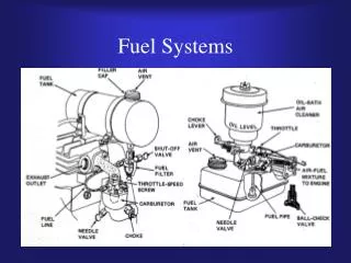
Fuel Systems
Fuel Systems. AF115 M. Westerman. Fuel System Components Common to both A/C. Fuel Tanks Vents Lines Measuring device Fuel Gauges Fuel tank selector Fuel Strainer. Fuel System Components Specific to N model A/C. Primer Carburetor. Fuel System Components Specific to S model A/C.

Fuel Systems
E N D
Presentation Transcript
Fuel Systems AF115 M. Westerman
Fuel System Components Common to both A/C • Fuel Tanks • Vents • Lines • Measuring device • Fuel Gauges • Fuel tank selector • Fuel Strainer
Fuel System Components Specific to N model A/C • Primer • Carburetor
Fuel System Components Specific to S model A/C • Fuel Reservoir • Auxiliary Fuel pump • Fuel Shut off valve (separate from selector) • Engine Driven Fuel Pump • Fuel/Air Control Unit • Fuel distribution valve • Fuel Flow Indicator
Fuel tanks • S Model • Integral tanks (part of the wing) • Riveted together with sealant between • Can hit the rib when checking fuel quantity giving inaccurate reading • N Model • Aluminium tanks strapped into wing between ribs
Fuel tanks cont’d… • Attached to fuel tanks: • Fuel caps • Fuel lines • Fuel quantity indicating system • Fuel caps • Both models have vented caps for each tank. • Allows air in or out?
Fuel Lines • Some carry air, others carry fuel • Fuel lines exit the tanks at the wing root, and there are two per tank • Extending from the front and back of the fuel tank, and going down through each door post • Venting lines extend overhead in the cabin and join the two tanks
Fuel lines Cont’d… • Air is drawn in from the vent located behind strut on left wing • S model has an additional vent line extending to the fuel reservoir • Before fuel leaving the tanks there is a coarse mesh to filter out any large particulate
Fuel Quantity • Both have a float and gear assembly to measure fuel • Float position is converted into an electrical resistance that can be used by a fuel gauge to determine fuel level
Tank Selector • Simply allows you to select which tank to feed fuel from to the engine • Both models have a Both, Left and Right position • N model there is an off position incorporated into this selector
Fuel Strainer • At the lowest point of the fuel system • Used to collect water and sediment from the system • Has a fine mesh screen inside to filter out larger debris • Is drained before each flight to rid the system of contaminants
N Model Components • Primer • Essentially a cylinder and a piston that only go through the intake and exhaust stroke • As you pull primer out, fuel is drawn into cylinder • As you push primer back in, fuel is ejected from cylinder and driven into three of the four cylinders • Why only three you ask!
Carburetor • Main principle fuel metering devices work from is Bernoulli • As speed increases, pressure decreases • Pressure decrease= vacuum • Venturi‘s are used to create this area of low pressure • How does air pass through venturi?
Float type carb • A small reservoir of fuel the metering unit draws from • The amount of fuel in the reservoir is controlled by a float (just like a toilet)
Carburetor cont’d… • Systems within a carburetor • Main metering • Idling • Mixture control • Accelerating
Main Metering • Comprised of • Venturi • Main metering jet • Butterfly valve • Fuel at tip of metering jet is level with that of the fuel chamber • As air flows past the venturi the vacuum draws fuel out of the metering jet
Idling • When butterfly valve is closed there is little if any pressure diff in venturi • At idle there will be a small idle metering jet that is above the butterfly valve • It can be adjusted to allow more or less fuel in while idling • If your a/c is idling too high or too low, it can be changed
Mixture control • A small valve is installed inline with the main metering jet • Allows you to control how much fuel is being allowed to enter the main metering jet
Accelerator Pump • When you increase throttle rapidly main metering jet can’t keep up with initial airflow • Similar to a primer • When you reduce throttle to idle cylinder fills up • When you increase throttle piston drives the fuel out of a secondary discharge nozzle
Problems • Cold Air and accelerating quickly • Accelerator pump and flooding • Carb ice • Can’t go upside down • Less efficient than fuel injection
S Model • Fuel Reservoir • Auxiliary Fuel pump • Fuel Shut off valve (separate from selector) • Engine Driven Fuel Pump • Fuel/Air Control Unit • Fuel distribution valve • Fuel Flow Indicator
Fuel Resevoir • Located under the floor of the passenger’s feet • Vented through the fuel tanks venting system • Allows for a continuous reliable source to draw from
Auxiliary Fuel Pump • Located beside of the reservoir • Providing required fuel pressure through lines for starting • Helps prevent vapour lock • A backup source for the engine driven pump
Aux Pump Cont’d… • Vane type is most commonly used however it does vary • Vanes offset so fuel gets in one side and forced out the other • Has a relief valve so over pressurization doesn’t occur
Engine Driven Fuel pump • Same idea as the electric pump but more regulated as it turns in time with the engine
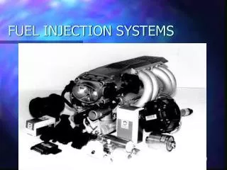
Fuel Air Control Unit • RSA type continuous flow fuel injection system used • Meaning fuel is continuously flowing through nozzles and put in the stream of metered air just before the intake port
Fuel air control unit cont’d… • From the engine driven fuel pump fuel flow into the fuel metering unit • Fuel metering unit consists mainly of mixture control valve, and an idle valve • First fuel is metered past the mixture valve (you control) • Second flows through the idle valve controlled by a mechanical linkage with the throttle
Fuel regulator • Uses both air metering forces and fuel metering forces to regulate the fuel to the divider • Ram air pushes the valve open while the venturi sucks the valve open • Pressure diff between inlet fuel pressure and metered fuel pressure will allow more fuel to flow through the main metering jet and through to the metered fuel
Fuel regulator cont’d… • Therefore the more the throttle is open, the more ram air there is and the lower the pressure is across the venturi
Flow divider • Once fuel is regulated it is sent to the fuel divider via a steel tube • Fuel divider has a spring loaded diaphragm that shuts the fuel off to the injectors is fuel pressure is not present • Fuel is split evenly to each injector • There is one injector per cylinder