Plastic Injection Molding
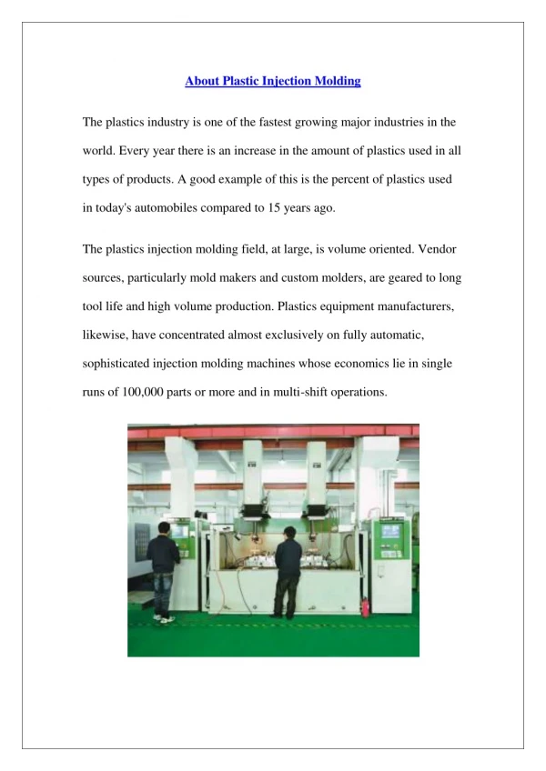
Plastic Injection Molding. Injection Molding. 3 major functional units; injection, mold, clamping. Plastic Injection Molding. is a manufacturing technique for making parts from thermoplastic and thermoset material s

Plastic Injection Molding
E N D
Presentation Transcript
Injection Molding 3 major functional units; injection, mold, clamping
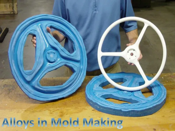
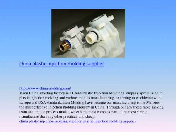
Plastic Injection Molding • is a manufacturing technique for making parts from thermoplastic and thermoset materials • In contrast to the extrusion (which makes continuous parts of constant cross section), injection molding make discrete parts (with complex and variable cross section) • Molten plastic is injected at high pressure into a mold, which is the inverse of the desired shape. • The mold is made from metal, usually either steel or aluminium • widely used for manufacturing a variety of parts, from the smallest component to entire body panels of cars
Plastic Injection Molding • The key to success in injection molding are to have; • Proper machine for good melting and injecting of the resin • The proper resin to appropriate part performance • A good mold for part definition and removal • Proper operation for efficient molding cycle (mold cycle depends on the design of the mold and manufacturing parameters)
The most commonly used thermoplastic materials are; • polystyrene (low-cost, lacking the strength and longevity of other materials) • ABS or acrylonitrile butadiene styrene (a co-polymer or mixture of compounds used for everything from Lego parts to electronics housings) • nylon (chemically resistant, heat-resistant, tough and flexible - used for combs) • polypropylene (tough and flexible - used for containers • PVC (more common in extrusions as used for pipes, window frames, or as the insulation on wiring where it is rendered flexible by the inclusion of a high proportion of plasticiser).
Injection Unit • Purpose: to liquify the plastic materials and then inject the liquid into mold • Resin is introduced through hopper • Some machines can have several hoppers (to fed filler, colorants, other additives)-Injection molding act as mixer • However, due to limited size of barrel, mixing capability is poor
Injection Unit • From hopper – hole (feed throat) • Barrel made of heavy steel cylinder to withstand the pressure and temperature involved in melting the resin • 2 types of system used in injection molding; • Reciprocating screw- similar to extruder screw but with unique reciprocating action • Ram injector
Injection Unit • Design of screw- similar to an extrusion screw • 3 sections; • Feed section- to advance the resin • Compression section- to melt the resin • Metering section- to homogenize the resin and pump it forward • The screw of injection molding machine is shorter than extruder, L/D ratios are 12:1 and 20:1 • Low L/D ratios suggest the mixing is less efficient in the injection molding machine • The compression ratio (diameter of root at feed zone to the diameter of root at metering zone) often in the range of 2:1 and 5:1 • Low compression ratio means less mechanical action is added during melting process
Injection Unit • Important measure of the size of an injection molding is weight of resin that can be injected, called shot size • Typical shot size range from 20g to 20 kg • Since shot size depends on the density of the plastic, PS has been chosed as the standard for rating the machine
Reciprocating Screw Injection Molding Machine • Resin is melt by mechanical shear and thermal energy from heaters • The molten resin is conveyed to a space at the end of the screw- collects in a pool • Here, the mold is closed
Reciprocating Screw Injection Molding Machine • The entire screw move forward and pushes the molten resin out through the end of barrel • To ensure the resin does not flow backward, a check valve or nonreturn valve is attached to the end of screw • Normally the screw will stay in the forward position, until resin began to harden in the mold
Reciprocating Screw Injection Molding Machine • Retraction of the screw, create space at the end of the screw • Cooling of the part in the mold, until it can be removed • While the part is cooling, the screw turns and melts additional resin
Reciprocating Screw Injection Molding Machine • Advantages • More uniform melting • Improved mixing or additives and dispersion throughout the resin • Lower injection pressure • Fewer stresses in the part • Faster total cycle
Ram Injection- Injection Molding Machine • In this type of injection molding, the resin is fed from a hopper into the barrel, and heated through thermal energy from the heaters • The molten resin is collect in a pool in a barrel celled injection chamber • The molten resin is then push forward by the action of plunger (ram or piston) • To five better mixing, the molten resin is pushed past a torpedo/spreader, impart shear to the melt
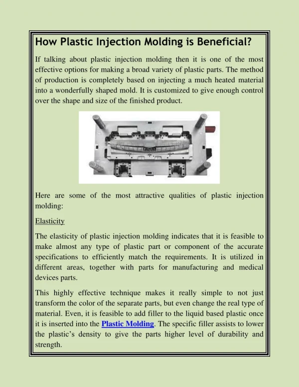
Molds • Designing and making mold for injection molding is more complicated than making extrusion die • Mold Parts – mold is placed in between stationary plate and the moveable plate
Molds • The connection from the injection unit to the mold is through the nozzle • The channel that run through the stationary plate of the mold is called the sprue channel (material that is in the channel is called the sprue) • The solid sprue is removed from the finished part assembly after the part is ejected from the mold • Resin flow from the sprue through the runner (connecting channel) to the mold cavities
Mold Bases • Assembly of various mold parts • Mold bases can be purchased as entire units, then the cavities are cut from A & B plates
Runners • Distribution system for the resin from the sprue to the cavities • Flow characteristics (viscosity), temperature and other factors are important in determining the runner diameter and length • If the diameter of the runner is too small or the length is too long,the resin can freeze in the runner before the mold is completely full • If the runner system is too large, excess material would be ejected and too much regrind created
If the resins have a high viscosity, larger runners are needed compared to low viscosity resin • The optimum flow of the resin through the runner system depends on the shape and diameter of the channel • Round channel give the best flow characteristics but difficult to machine • Machining cost can be reduce by machining one side of the mold plates • Better shape where the depth of the channel is at least two-thirds the size of the width and the sides are tapered between 2 to 5º.
Secondary Runners • Secondary runner channel are used for multicavity molds • The flow into the secondary channel should be streamlined (angle in flow direction) • The streamlined minimizes shear on the resin
Gates • The end of runner and the entry path into the cavity • The gate shape can also affect the filling of the cavity, dimension and properties of the parts • Gate is the most restricted point in injection molding system, i.e. for reinforcement and filler + polymer systems
Gate Design • Small rectangular opening at the end of the runner channel, connect to the edge of cavity • Edge gate can be below the parting line if the channel and part are also below the parting line • Or it can be symetricaly about the parting line, if the runner channel and part are at both side of parting line Edge gate
Submarine Gate • Starts from the edge of the runner, and goes into the cavity edge at an angle • It narrows to a point as it moves from the runner to the cavity • The advantage; separation of the parts and the runner is automatic • Disadvantage; gate cannot be used for some resins because of high shear Submarine Gate
Tab Gate • By connecting the runner directly into the cavity with no reduction in runner cross-section • Used for very large parts where a reduction in flow would disturb the resin’s flow pattern and might result inadequate flow into the cavity
Fan Gate • Made by reducing the thickness and not the diameter of the runner channel as it goes into the cavity • Used for intermediate size, and when reinforcement in the resin cannot flow through the edge gate
Ring Gate • Used to make hollow cylinder parts • The ring gate covers the entire top of the cylinder part so that the resin flow is downward into the wall of the part
Cavities • Are actual molding locations • Resin enter the cavities through gate, fills the cavities, and cools to form the solid. The parts are ejected and finished • Cavities are the heart of the molding process, and must be precisely prepared • The shape of the cavities determines the shape of the part
Materials & Product Consideration • Almost all thermoplastic can be injection molded • Resin with low melt viscosity is required; so that the flow through runner, gate, cavity – easily done with minimum injection pressure • Resin with injection molding grades have low molecular weight and narrow molecular weight distribution
Shapes • Hollow parts can be created by allowing the moveable plate to protrude into the cavity of the stationary plate
Shapes • Threads can be placed on the inside of a part by using a core pin that is inserted into the cavity where the threads are desired
Shapes • A hollow part with a hole on the side is even more complicated (the core pin is used) • The core pin slide into position after the mold is closed • The core pin seals against the surface of the moveable plate, prevent flow of resin into the area