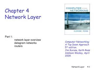
Network Layer: a. Forwarding
This overview delves into the principles and implementation of network layer services, including forwarding, routing, scale, and instantiation in various networks. It covers virtual circuits, ATM, IP addresses, NAT, IP fragmentation, ICMP, and IPv6.

Network Layer: a. Forwarding
E N D
Presentation Transcript
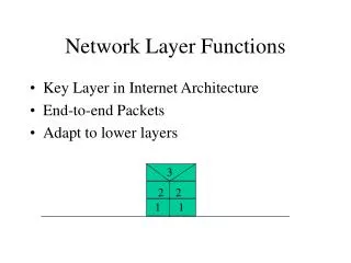
Goals: understand principles behind network layer services: forwarding routing (path selection) dealing with scale instantiation and implementation in the Internet and in other types of networks Overview: network layer services VC network operation ATM IP addresses & their usage NAT IP header IP fragmentation ICMP IPv6 Network Layer: a. Forwarding Ch. 4: Network Layer - Forwarding
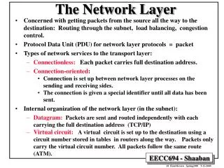
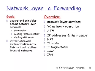
Network Layer objectives • Transport packet from source to dest. • Net layer in all hosts, routers Basic functions: • Forwarding • move packets from source to destination through routers • Routing • prepare info (table) that enables finding a path for every packet/ data stream • Call setup (VC only, see later) • find path for a data session before data transfer starts • keep record of it in routers “Data plane” “Control plane” Ch. 4: Network Layer - Forwarding
Routing Interplay between routing and forwarding routing algorithm Build routing tables local routing table header value output link 0100 0101 0111 1001 3 2 2 1 value in arriving packet’s header 1 0111 2 3 Forwarding Move packets from input link to output link Ch. 4: Network Layer - Forwarding
Q: What service modelfor “channel” transporting packets from sender to receiver? guaranteed bandwidth? preservation of inter-packet timing (no jitter)? loss-free delivery? in-order delivery? congestion feedback to sender? Network service model The most important abstraction provided by network layer: ? ? virtual circuit or datagram? ? service abstraction Ch. 4: Network Layer - Forwarding
Signaling used to set up, maintain, teardown VC application transport network data link physical application transport network data link physical Virtual circuits: signaling protocols • Principle • prepare a path (= VC) before moving data • each direction is a separate path • used in ATM, frame-relay, X.25 • not used in today’s Internet • but Cisco’s MPLS builds a VC service over IP 6. Receive data 5. Data flow begins 4. Call connected 3. Accept call 1. Initiate call 2. incoming call path recorded more path details Ch. 4: Network Layer - Forwarding
Virtual Circuit: call setup • Path preparation + resource allocation: • Call setup message flows from source to destination. • path recorded at this time • Path determination (routing): • Source based or network based. • Msg may indicate required resources: • BW, latency, buffer, etc. • A router can either: • accept (and commit required resources) or reject • Path accepted if all routers accept. Ch. 4: Network Layer - Forwarding
Virtual Circuit: Identifiers • Forward call-setup pass: • each router allocates an ID for the VC • intended for incoming (I/C) packets of the VC • records it + the preceding &following node of path • Backward call-setup pass: • each router tells predecessor its ID for the VC • first predecessor is the originating host • ID will be used for this VC on the link between them • lists in the I/C port’s fwding table the I/C VC-ID and the corresponding O/G port +O/G ID • Runtime: when receiving a packet with an ID : • find, in the I/C port’s forwarding table, the I/C ID’s record • read from it the outgoing port & the O/G ID • send packet on the required port with new ID . Ch. 4: Network Layer - Forwarding
VC : identifiers preparation • Example: call setup stage BW=1Mb BW=1Mb BW=1Mb 1 2 2 1 • Summary: • VC-ID has a separate value on each link • determined by the receiving router and sent by signaling to sending node Ch. 4: Network Layer - Forwarding
VC : identifiers usage • Example: runtime stage VCid=38 VCid=98 VCid=22 2 1 2 1 Ch. 4: Network Layer - Forwarding
no call setup at network layer routers: no state about end-to-end connections no network-level concept of “connection” packets typically routed using destination host ID packets between same source-dest pair may take different paths, if routing tables change application transport network data link physical application transport network data link physical Datagram networks: Internet model 1. Send data 2. Receive data Ch. 4: Network Layer - Forwarding
ATM: overview • Asynchronous Transfer Mode • Fixed packets size: called cells • 53 bytes = 5 header + 48 data • All virtual-circuit based • Types of virtual circuits • “virtual circuits” aggregated into “virtual paths” • Permanent or switched • virtual paths used to reduce size of forwarding tables • Architecture is QoS-focused • Service Quality types: CBR, VBR, ABR, UBR • Constant/Variable/Arbitrary/Unspecified – Bit Rate • Access traffic policing • Typical tool: leaky-bucket access control Ch. 4: Network Layer - Forwarding
Network Layer Quality of Service Guarantees ? Network Architecture Internet ATM ATM ATM ATM Service Model best effort CBR VBR ABR UBR Congestion feedback no (inferred via loss/delay) no congestion no congestion yes no Bandwidth none constant rate guaranteed rate guaranteed minimum none Loss no yes yes no no Order no yes yes yes yes Timing no yes yes no no • Internet model isbeing extended: Intserv, Diffserv • multimedia networking ATM: Asynchronous Transfer Mode; CBR: Constant Bit Rate; V: Variable; A: available; U: Unspecified Ch. 4: Network Layer - Forwarding
Internet (Datagram) data exchange among hosts (mostly) “elastic” service, no strict timing req. “smart” end systems can adapt, perform control, error recovery simple inside network, complexity at “edge” many link types different characteristics uniform service difficult Datagram benefit: Simplicity ATM (VC) evolved from telephony but supports also data human conversation: strict timing &reliability requirements svc guarantees needed “dumb” end systems telephones complexity inside network VC Benefits: Fast forwarding Traffic Engineering. In order delivery Datagram or VC network: why? Ch. 4: Network Layer - Forwarding
IP Addressing Scheme We need an address to uniquely identify each destination Routing scalability requires flexibility in aggregation of destination addresses we should be able to aggregate a set of destinations as a single routing unit necessary for routing table scalability Preview: the unit of routing in the Internet is a network - the destinations in the routing protocols and tables are networks Ch. 4: Network Layer - Forwarding
IP address: 32-bit identifier for host or router interface (NIC) interface: connection between host/router and physical link router’s typically have multiple interfaces a host has typically a single interface IP addresses associated with interface, nothost, or router 223.1.1.2 223.1.2.2 223.1.2.1 223.1.3.2 223.1.3.1 223.1.3.27 IP Addressing: introduction 223.1.1.1 223.1.2.9 223.1.1.4 223.1.1.3 223.1.1.1 = 11011111 00000001 00000001 00000001 223 1 1 1 Ch. 4: Network Layer - Forwarding
IP address is divided into two parts: network prefix K high order bits host number remaining low order bits This partitioning of the address depends on the contextnetworkin which we see this NIC networks are nested inside each other IP Addressing 223.1.1.1 223.1.2.1 223.1.1.2 223.1.2.9 223.1.1.4 223.1.2.2 223.1.3.27 223.1.1.3 LAN 223.1.3.2 223.1.3.1 Qn: What is the router’s IP address in the drawing we see? Ch. 4: Network Layer - Forwarding
IP network terminology: a Subnet is: a set of devices that can physically reach each other without intervening router(s) e.g. a LAN a Network is: a subnet , or: the union of several subnets that are interconnected by links What is a network in IP view? 223.1.1.1 223.1.2.1 223.1.1.2 223.1.2.9 223.1.1.4 223.1.2.2 223.1.3.27 223.1.1.3 LAN 223.1.3.2 223.1.3.1 three subnets (LANs) 223.1.1.*, 223.1.2.*, 223.1.3.*, together they form a larger network with prefix 223.1 (16 bits)(OR MORE bits?) Ch. 4: Network Layer - Forwarding
IP Address Structure (CIDR method) • the network prefixconsists of the K most significant bits of the address • in some cases it is called the subnet prefix (see subnets below) • the host number= the remaining (32-K) bits • the size Kof the network prefix differs and must be specified in each case. Two methods used for this: • network mask has all 1‘s in the prefix part and all 0’s elsewhere • short notation is /K (also called the CIDR notation) Exercise 1 • write the following IP address in dotted decimal notation • specify corresponding netwk mask (binary and dotted decimal) • show network prefix & host # parts of that address (binary) 11001000 00010111 00010001 10110101 /23 see solutions at end of chapter (in Extra slides) Ch. 4: Network Layer - Forwarding
Special Types of IP Address • network broadcast address: host # = 11...1 • means: all the hosts in the network specified in address prefix • used only as destination address of packets • if dest. address = 11… 1 (32 1’s), broadcast on sender’s subnet • network address : host # = 0 (all zeros) • means: the whole network (used onlyin routing tables) • therefore the IP address of a host/router can not have host number = 0 or = “all ones” Exercise 2 • write the network address of the network from Exercise 1 • write the broadcast address for that network • how many IP host addresses are possible in that network? • write host & network address with /K notation • write the first and last host address on that network Ch. 4: Network Layer - Forwarding
Recipe To determine the subnets of a network, detach each interface from its host or router, creating islands of isolated networks. Each isolated network is a subnet. Subnets Example Network 223.1.0.0 / 21 Divide network into subnets and give an address to each subnet Ch. 4: Network Layer - Forwarding
Solution of Example Stage 2 Network 223.1.0.0 / 21 Stage 1 Subnet 223.1.1.0 / 24 Subnet 223.1.2.0 / 24 223.1.1.1 223.1.2.1 223.1.1.2 223.1.2.9 223.1.1.4 223.1.3.27 223.1.1.3 223.1.2.2 223.1.3.2 223.1.3.1 Subnet 223.1.3.0 / 24 Subnets: /24 Ch. 4: Network Layer - Forwarding
How many subnets? Write an address for each subnet,including /K Write an address for the whole network,including /K Whole network: 223.1.0.0/20 Subnets 223.1.1.2 Subnet 223.1.1.0/24 223.1.1.1 223.1.1.4 223.1.1.3 223.1.7.2 223.1.9.2 Subnet223.1.7.0/24 Subnet223.1.9.0/24 223.1.9.1 223.1.7.1 223.1.8.1 223.1.8.2 Subnet223.1.8.0/24 223.1.2.6 223.1.3.27 223.1.2.2 223.1.3.2 223.1.3.1 223.1.2.1 Subnet223.1.3.0/24 Subnet223.1.2.0/24 Ch. 4: Network Layer - Forwarding
multicast address (*) 1110 network host 110 network 10 host IP Addresses given notion of “network”, let’s re-examine IP addresses: “classful” addressing: (does not need mask or /K indicator) class 1.0.0.0 to 127.255.255.255 A network 0 host 128.0.0.0 to 191.255.255.255 B 192.0.0.0 to 223.255.255.255 C 224.0.0.0 to 239.255.255.255 D 32 bits (*) this range used as multicast also in CIDR method Ch. 4: Network Layer - Forwarding
host part network part 11001000 0001011100010000 00000000 200.23.16.0/23 IP addressing: CIDR • classful addressing: • inefficient use of address space, address space exhaustion • e.g., class B net allocated enough addresses for 65K hosts, even if only 2K hosts in that network • CIDR:Classless InterDomain Routing • network portion of address of arbitrary length • address format: a.b.c.d/x, where x is # bits in network portion of address • Requires inclusion of mask or “/K” in routing table Ch. 4: Network Layer - Forwarding
IP addresses: how to get one? Hosts (host number): • hard-coded by system admin in a file • Can see in IPConfig • DHCP:Dynamic Host Configuration Protocol: dynamically get address: “plug-and-play” • host broadcasts “DHCP discover” msg • DHCP server responds with “DHCP offer” msg • host requests IP address: “DHCP request” msg • DHCP server sends address: “DHCP ack” msg • this is the common practice in LAN (why?) • in home access: same procedure using PPP protocol Ch. 4: Network Layer - Forwarding
IP addresses: how to get one? Network (network prefix+mask): • get allocated portion of ISP’s address space: ISP's block 11001000 00010111 00010000 00000000 200.23.16.0/20 Organization 0 11001000 00010111 00010000 00000000 200.23.16.0/23 Organization 1 11001000 00010111 00010010 00000000 200.23.18.0/23 Organization 2 11001000 00010111 00010100 00000000 200.23.20.0/23 ... ….. …. …. Organization 7 11001000 00010111 00011110 00000000 200.23.30.0/23 Ch. 4: Network Layer - Forwarding
IP addresses: how to get one? ISP • Gets a block of addresses from ICANN: A: ICANN: Internet Corporation for Assigned Names and Numbers • allocates addresses • manages DNS • assigns domain names, resolves disputes • allocates codes for the various protocols Ch. 4: Network Layer - Forwarding
200.23.16.0/23 200.23.18.0/23 200.23.30.0/23 200.23.20.0/23 . . . . . . Hierarchical addressing: route aggregation Hierarchical addressing allows efficient advertisement of routing information: Organization 0 Organization 1 “Send me anything with addresses beginning 200.23.16.0/20” Organization 2 Fly-By-Night-ISP Internet Organization 7 “Send me anything with addresses beginning 199.31.0.0/16” ISPs-R-Us Ch. 4: Network Layer - Forwarding
200.23.16.0/23 200.23.18.0/23 200.23.30.0/23 200.23.20.0/23 . . . . . . Hierarchical addressing: specific routes Organization 1 moved to ISPs-R-Us, but kept old address space ISPs-R-Us advertizes a more specific route to Organization 1 Organization 0 “Send me anything with addresses beginning 200.23.16.0/20” Organization 2 Fly-By-Night-ISP Internet Organization 7 “Send me anything with addresses beginning 199.31.0.0/16 or 200.23.18.0/23” ISPs-R-Us Organization 1 Ch. 4: Network Layer - Forwarding
Routingtable 4 billion possible entries (*) Destination Address RangeLink Interface 11001000 00010111 00010000 00000000 through 0 11001000 00010111 00010111 11111111 11001000 00010111 00011000 00000000 through 1 11001000 00010111 00011000 11111111 11001000 00010111 00011001 00000000 through 2 11001000 00010111 00011111 11111111 otherwise 3 (*) true for IPv4; in IPv6 MUCH more Ch. 4: Network Layer - Forwarding
Longest prefix matching Network /K Link Interface 11001000 00010111 0001000000000000/210 11001000 00010111 0001100000000000/241 11001000 00010111 0001010000000000/242 00000000 00000000 00000000 00000000 /03 Network Link Interface 200.23.16.0 /210 200.23.24.0 /24 1 200.23.20.0 /24 2 otherwise 3 Routing table Examples: Which interface will be used by this router for following dest addresses? (a) DA: 11001000 00010111 00010110 10100001 (b) DA: 11001000 00010111 00010100 10101010 (c) DA: 11001000 00010111 00011100 10111110 (d) DA: 11001000 00010111 00011000 11101010 Network Layer
IP datagram: A B E source IP addr misc fields dest IP addr data Dest. Net. next router Nhops 223.1.1 1 223.1.2 223.1.5.2 2 223.1.3 223.1.5.2 2 Getting a datagram from source to dest. routing table in R 223.1.1.4 • datagram remains unchanged (*), as it travels source to destination • forwarding based on addr fields only • Main field : dest. IP addr 223.1.5.1 223.1.1.1 R S 223.1.2.1 223.1.1.2 223.1.5.2 223.1.2.9 223.1.2.2 223.1.3.27 223.1.1.3 223.1.3.2 223.1.3.1 (*) almost Ch. 4: Network Layer - Forwarding
E B A Getting a datagram from source to dest. misc fields A’s ARP Table: 223.1.1.3 => 223.1.1.4 => Etc. A’s IPConfig: IP Addr: 223.1.1.1 Subnet /K = 24 (*) Dflt Gtwy: 223.1.1.4 data 223.1.1.1 223.1.1.3 Starting at A, given IP datagram addressed to B: • A looks up its /K(*) in IPConfig • Compares first K bits in dest address with those in its own • find B is on same net. as A • same prefix same subnet • link layer will send datagram directly to B in link-layer frame • using ARP table/protocol • B and A are directly connected • (*) in the form of subnet mask 223.1.1.4 223.1.5.1 223.1.1.1 S R 223.1.2.1 223.1.1.2 223.1.5.2 223.1.2.9 223.1.2.2 223.1.3.27 223.1.1.3 223.1.3.2 223.1.3.1 (*) subnet mask = 225.225.225.0 Ch. 4: Network Layer - Forwarding
E B A Dest. Net. Next router Port Hops 223.1.1.0 /24 a 1 223.1.2.0 /24 223.1.5.2 b 2 223.1.3.0 /24 223.1.5.2 b 2 Getting a datagram from source to dest. Routing Table misc fields data 223.1.1.1 223.1.2.2 Starting at A, dest. E: • look up network address of E • A finds E on another network • /K prefixes don’t match • sends to default router R • 223.1.1.4 listed in IPConfig • R’s routing table says: next hop router to E is 223.1.5.2: S • link layer sends datagram to router 223.1.5.2 as link-layer frame using ARP & Ethernet • datagram arrives at 223.1.5.2 • cont. on next slide.. a 223.1.1.4 223.1.5.1 223.1.1.1 S R b 223.1.2.1 223.1.1.2 223.1.5.2 223.1.2.9 a b 223.1.2.2 223.1.3.27 223.1.1.3 c 223.1.3.2 223.1.3.1 Ch. 4: Network Layer - Forwarding
B E A Dest. Net. Next router Port Hops 223.1.1.0 /24 223.1.5.1 a 2 223.1.2.0 /24 b 1 223.1.3.0 /24 c 1 Getting a datagram from source to dest. misc fields data 223.1.1.1 223.1.2.2 Arrived at 223.1.5,2, continuing to 223.1.2.2 • look up network address of E • E on subnet directly attached to router’s interface b • link layer sends datagram to 223.1.2.2 inside link-layer frame via I/F b (223.1.2.9) • datagram arrives at 223.1.2.2!!! (hooray!) • Qn: What tables consulted in last two bullets? a 223.1.1.4 223.1.5.1 223.1.1.1 S R b 223.1.2.1 223.1.1.2 223.1.5.2 223.1.2.9 a b 223.1.2.2 223.1.3.27 223.1.1.3 c 223.1.3.2 223.1.3.1 Ch. 4: Network Layer - Forwarding
Network Address Translation (NAT): Outline • A private network uses just one public IP address as far as outside world is concerned • Each device on the private network is assigned a private IP address rest of Internet private network (e.g., home network) 192.168.1.0/24 192.168.1.2 192.168.1.1 192.168.1.3 138.76.29.7 192.168.1.4 Here Here Datagrams with source or destination in this network have 192.168.1/24 address for source /destination (as usual) All datagrams leaving private network have same single source NAT IP address: 138.76.29.7, different source port numbers Ch. 4: Network Layer - Forwarding
NAT: Implementation NAT router must: for outgoing datagrams: replace (source IP address, port #) of every outgoing datagram by(NAT IP address, new port #) . . . remote clients/servers will respond using (NAT IP address, new port #) as destination addr. remember (in NAT translation table) every (source IP address, port #) to (NAT IP address, new port #) translation pair for incoming datagrams: replace (NAT IP address, new port #) in dest fields of every incoming datagram with corresponding (source IP address, port #) stored in NAT table Ch. 4: Network Layer - Forwarding
NAT: Network Address Translation 3 1 2 4 S: 192.168.1.2, 3345 D: 128.119.40.186, 80 S: 138.76.29.7, 5001 D: 128.119.40.186, 80 1: host 192.168.1.2 sends datagram to 128.119.40.186, 80 2: NAT router changes datagram source addr from 192.168.1.2, 3345 to 138.76.29.7, 5001, updates table S: 128.119.40.186, 80 D: 192.168.1.2, 3345 S: 128.119.40.186, 80 D: 138.76.29.7, 5001 NAT translation table WAN side addr LAN side addr 138.76.29.7, 5001 192.168.1.2, 3345 …… …… 192.168.1.2 192.168.1.1 192.168.1.3 138.76.29.7 192.168.1.4 4: NAT router changes datagram dest addr from 138.76.29.7, 5001 to 192.168.1.2, 3345 after consulting translation table 3: Reply arrives dest. address: 138.76.29.7, 5001 Ch. 4: Network Layer - Forwarding
NAT: Advantages No need to be allocated range of addresses from ISP: - just one public IP address is used for all devices 16-bit port-number field allows 60,000 simultaneous connections with a single LAN-side address ! can change ISP without changing addresses of devices in private network can change addresses of devices in private network without notifying outside world Devices inside private net not explicitly addressable, visible by outside world (a security plus) Ch. 4: Network Layer - Forwarding
NAT: Drawbacks If both hosts are behind distinct NATs, they will have difficulty establishing connection NAT is controversial: violates layer modularity principle: routers should process up to only layer 3 causes problem for some application protocols: if application writes an explicit IP address within the L5 header, the peer application will get a useless internal-NAT IP address as an argument proper address shortage solution :IPv6 ! Ch. 4: Network Layer - Forwarding
32 bits IP datagram format see also Extra slides IP protocol version number total datagram length (bytes) type of service head. len ver header length (# of 32-bit words) total length for fragmentation/ reassembly (**) fragment offset flgs 16-bit identifier max number remaining hops (decremented at each router) time to live Header checksum protocol quality of svc (*) 32 bit source IP address (*) seldom used 32 bit destination IP address which upper layer prot. should receive payload E.g. timestamp, record route taken, specified list of routers to use. Options (if any) & padding how much overhead with TCP? • 20 bytes of TCP • + 20 bytes of IP • = 40 bytes + app layer overhead data (variable length, typically a TCP or UDP segment) (**) we skip the details Network Layer
IPv6 • Initial motivation:32-bit address space soon to be completely allocated. • Additional motivation: • IPv6 header format helps speed processing • IPv6 datagram format: • 16-byte (128 bit) IP address • fixed-length 40 byte header • no options allowed inside the header • each option gets its own header after the main IP header • fragmentation discouraged • allowed only using an options header Network Layer
40 bytes header IPv6 Datagram Format Priority: identify priority among datagrams in flow Flow Label: identify datagrams in same “flow.” (designed to enable Virtual Circuits over IP ). Next header: identify upper layer protocol that should receive “data“ (“protocol” could also be an option type of IPv6) bytes = TTL Network Layer
Transition From IPv4 To IPv6 • Not all routers can be upgraded simultaneously • How will the network operate with mixed IPv4 & IPv6 routers? • Tunneling:IPv6 datagrams are carried as payload in IPv4 datagrams when travelling through IPv4 routers • source and destination network are IPv6, but need to transitan existing IPv4 network • How is tunneling done? • gateway router in source network takes the IPv6 datagram as payload and encapsulates it into an IPv4 datagram • i.e. adds an IPv4 header in front of it • the IPv4 destination is the gateway router of the destination network, which removes the IPv4 header and routes by IPv6 • Gateway router must support IPv4, IPv6 and tunneling Network Layer
Flow: X Src: A Dest: F data Flow: X Src: A Dest: F data Flow: X Src: A Dest: F data Flow: X Src: A Dest: F data F B A C D E B A E F Src:B Dest: E Src:B Dest: E Tunneling tunnel Logical view: IPv4 IPv4 IPv6 IPv6 IPv6 IPv6 IPv6 IPv6 Island IPv6 Island IPv4 IPv4 Physical view: IPv6 IPv6 IPv4 IPv4 A-to-B: IPv6 E-to-F: IPv6 B-to-C: IPv6 inside IPv4 B-to-C: IPv6 inside IPv4 Network Layer
Usage of Tunneling • Tunneling is used to move a packet between similar networks A, B through a network Cthat is unable to understand its L3 header • Possible reasons: • C uses a different protocol (e.g. IPv6 vs IPv4) • A wants to encipher the data and the header(VPN application) • All networks use same protocol, but the destination node is currently at a foreign networkand wishes to use its usual IP address.(Mobile IP application) Network Layer
IPv6 status report • Operating systems – • wide support – early 2000 • Windows (2000, XP, Vista), BSD, Linux, Apple • Networking infrastructure • Cisco • Deployment • Slow • Penetration • Host - minor (less than 1%) • Used in 2008 in China Olympic games • Motivation: CIDR & NAT Ch. 4: Network Layer - Forwarding
Extra Ch. 4: Network Layer - Forwarding
network links have MTU (max.transfer size) - largest possible link-level frame. different link types, different MTUs large IP datagram divided (“fragmented”) within net one datagram becomes several datagrams “reassembled” only at final destination IP header bits used to identify, order related fragments IP Fragmentation & Reassembly fragmentation: in: one large datagram out: 3 smaller datagrams reassembly Ch. 4: Network Layer - Forwarding
length =1500 length =1040 length =1500 length =4000 ID =x ID =x ID =x ID =x fragflag =0 fragflag =0 fragflag =1 fragflag =1 offset =0 offset =185 offset =0 offset =370 One large datagram becomes several smaller datagrams IP Fragmentation and Reassembly Example • 4000 byte datagram • MTU = 1500 bytes 1480 bytes in data field offset = 1480/8 Ch. 4: Network Layer - Forwarding