Download
1 / 42
420 likes | 445 Vues
Introduction to Wireless Networking. Dimitrios Koutsonikolas 09/05/2018 These slides contain material developed by Lili Qiu for CS386W at UT Austin and by J.F Kurose and K.W. Ross. (Tentative) Grading. 2 credits. 3 credits. Paper presentations (2): 45% (25%+20%)

E N D
Introduction to Wireless Networking Dimitrios Koutsonikolas 09/05/2018 These slides contain material developed by Lili Qiu for CS386W at UT Austin and by J.F Kurose and K.W. Ross
(Tentative) Grading 2 credits 3 credits Paper presentations (2): 45% (25%+20%) Related work surveys (2): 30% Class participation: 30% Discussions: 20% Classmate evaluation: 10% No credit for simply showing up! • Paper presentations (2): 60% (35%+25%) • Related work survey: 15% • Class participation: 30% • Discussions: 20% • Classmate evaluation: 10% • No credit for simply showing up! The final grade is S/U. To receive an S grade, you have to score at least 70%
Application: supporting network applications FTP, SMTP, HTTP Transport: data transfer between processes TCP, UDP Network: routing of datagrams from source to destination IP, routing protocols Link: data transfer between neighboring network elements Ethernet, WiFi Physical: bits “on the wire” Coaxial cable, optical fibers, radios application transport network link physical Internet Protocol Stack
application transport network link physical Multiple Access Protocols
Multiple Access protocols • single shared broadcast channel • two or more simultaneous transmissions by nodes: interference • collision if node receives two or more signals at the same time multiple access protocol • distributed algorithm that determines how nodes share channel, i.e., determine when node can transmit
Ideal Multiple Access Protocol Broadcast channel of rate R bps 1. when one node wants to transmit, it can send at rate R. 2. when M nodes want to transmit, each can send at average rate R/M 3. fully decentralized: • no special node to coordinate transmissions • no synchronization of clocks, slots 4. simple
MAC Protocols: a taxonomy Three broad classes: • Channel Partitioning • divide channel into smaller “pieces” (time slots, frequency, code) • allocate piece to node for exclusive use • Random Access • channel not divided, allow collisions • “recover” from collisions • “Taking turns” • nodes take turns, but nodes with more to send can take longer turns
Channel Partitioning MAC protocols: TDMA TDMA: time division multiple access • access to channel in "rounds" • each station gets fixed length slot (length = pkt trans time) in each round • unused slots go idle • example: 6-station LAN, 1,3,4 have pkt, slots 2,5,6 idle 6-slot frame 3 3 4 4 1 1
Channel Partitioning MAC protocols: FDMA FDMA: frequency division multiple access • channel spectrum divided into frequency bands • each station assigned fixed frequency band • unused transmission time in frequency bands go idle • example: 6-station LAN, 1,3,4 have pkt, frequency bands 2,5,6 idle time frequency bands FDM cable
Random Access Protocols • When node has packet to send • transmit at full channel data rate. • Two or more transmitting nodes ➜ “collision”, • Random access MAC protocol specifies: • how to detect collisions • how to prevent collisions • how to recover from collisions (e.g., via delayed retransmissions) • Examples of random access MAC protocols: • slotted ALOHA • ALOHA • CSMA, CSMA/CD, CSMA/CA
CSMA (Carrier Sense Multiple Access) CSMA: listen before transmit: If channel sensed idle: transmit entire frame • If channel sensed busy, defer transmission • human analogy: don’t interrupt others!
CSMA collisions spatial layout of nodes collisions can still occur: propagation delay means two nodes may not hear each other’s transmission collision: entire packet transmission time wasted note: role of distance & propagation delay in determining collision probability
CSMA/CD (Collision Detection) CSMA/CD: carrier sensing, deferral as in CSMA • collisions detected within short time • colliding transmissions aborted, reducing channel wastage • Collision detection: • easy in wired LANs: measure signal strengths, compare transmitted, received signals • difficult in wireless LANs: received signal strength overwhelmed by local transmission strength
application transport network link physical PHY Layer
Wireless Link Characteristics Wireless is a broadcast medium! Differences from wired link …. • decreased signal strength: radio signal attenuates as it propagates through matter (path loss) • interference from other sources: standardized wireless network frequencies (e.g., 2.4 GHz) shared by other devices (e.g., phone); devices (motors, microwaves) interfere as well • multipath propagation (fading): radio signal reflects off objects or ground, arriving at destination at slightly different times • Reflection • Diffraction • Scattering Signal Strength space
Impact of Multipath Propagation Direct signal Reflected signal Received signal
Wireless Link Characteristics (2) – Fading • Channel characteristics change over time and location • e.g., movement of sender, receiver and/or scatters • quick changes in the power received (short term/fast fading) • slow changes in the average power received (long term/slow fading) long term fading power t short term fading
Received Signal Power (dBm) path loss slow fading fast fading log (distance) Typical Picture
Signal Propagation Ranges • Transmission range • communication possible • low error rate • Detection range • detection of the signal possible • no communication possible • Interference range • signal may not be detected • signal adds to the background noise sender transmission distance detection interference
Signal, Noise, and Interference • Signal (S) • Noise (N) • Includes thermal noise and background radiation • Interference (I) • Signals from other transmitting sources • SINR = S/(N+I) (sometimes also denoted as SNR) • Large SINR = easier to extract signal from noise
dB and Power conversion • dB • Denote the difference between two power levels • (P2/P1)[dB] = 10 * log10 (P2/P1) • P2/P1 = 10^(A/10) • Example 1: P2 = 10 P1, P2/P1=10dB • Example 2: P2/P1 = 33dB, P2 = 2000 P1 • dBm and dBW • Denote the power level relative to 1 mW or 1 W • P[dBm] = 10*log10(P/1mW) • P[dBW] = 10*log10(P/1W) • Example: P = 0.001mW = -30dBm, P = 100W = 20dBW 10dB: factor of 10 3dB: factor of 2
Wireless Link Characteristics (3) 10-1 • SNR: signal-to-noise ratio • larger SNR – easier to extract signal from noise • SNR versus BER tradeoffs • given physical layer: increase power -> increase SNR -> decrease BER • given SNR: choose physical layer that meets BER requirement, giving highest throughput 10-2 10-3 10-4 BER 10-5 10-6 10-7 10 20 30 40 SNR(dB) QAM256 (8 Mbps) QAM16 (4 Mbps) BPSK (1 Mbps)
base station, mobile dynamically change transmission rate (physical layer modulation technique) as mobile moves, SNR varies Rate Adaptation 10-1 10-2 10-3 BER 10-4 10-5 10-6 10-7 10 20 30 40 SNR(dB) 1. SNR decreases, BER increases as node moves away from base station QAM256 (8 Mbps) QAM16 (4 Mbps) BPSK (1 Mbps) operating point 2. When BER becomes too high, switch to lower transmission rate but with lower BER
AP AP Internet 802.11 LAN architecture • wireless host communicates with base station • base station = access point (AP) • Basic Service Set (BSS) (aka “cell”) in infrastructure mode contains: • wireless hosts • access point (AP): base station • ad hoc mode: hosts only hub, switch or router BSS 1 BSS 2
802.11b 2.4-2.5 GHz unlicensed spectrum up to 11 Mbps 802.11a 5-6 GHz range up to 54 Mbps 802.11g 2.4-2.5 GHz range up to 54 Mbps 802.11n: multiple antennae 2.4-2.5 and 5-6 GHz range up to 600 Mbps MIMO Frame aggregation Channel bonding 802.11ac 5-6 GHz range up to 3.4 Gbps MU-MIMO IEEE 802.11 Wireless LANs • all use CSMA/CA for multiple access
802.11: Channels • 802.11b/g: 2.4GHz-2.485GHz spectrum divided into 11 channels at different frequencies • AP admin chooses frequency for AP • interference possible: channel can be same as that chosen by neighboring AP! • 802.11a: 24 non-overlapping channels Only 3 non-overlapping channels!
802.11: Association • host must associate with an AP • scans channels, listening for beacon frames containing AP’s name (SSID) and MAC address • selects AP to associate with • may perform authentication • will typically run DHCP to get IP address in AP’s subnet
4 3 2 3 2 2 1 1 1 802.11: passive/active scanning BBS 1 BBS 1 BBS 2 BBS 2 AP 1 AP 1 AP 2 AP 2 H1 H1 Active Scanning: • Probe Request frame broadcast from H1 • Probes response frame sent from APs • Association Request frame sent: H1 to selected AP • Association Response frame sent: H1 to selected AP Passive Scanning: • beacon frames sent from APs • association Request frame sent: H1 to selected AP • association Response frame sent: H1 to selected AP
B A C C C’s signal strength A’s signal strength B A space IEEE 802.11 multiple access • 802.11: CSMA - sense before transmitting • Differences from Ethernet • No collision detection (CD)! • Difficult to receive (sense collisions) when transmitting due to weak received signals (fading) • Can’t sense all collisions in any case: hidden terminal, fading • Goal: avoid collisions: CSMA/C(ollision)A(voidance) • Link layer ACKnowledgments/Retransmissions (ARQ) • High bit error rates
DIFS data SIFS ACK IEEE 802.11 MAC Protocol: CSMA/CA 802.11 sender 1 if sense channel idle for DIFSthen transmit entire frame (no CD) 2 if sense channel busy then 2.1 start random backoff time timer counts down while channel idle, freezes when busy, resumes if idle for DIFS transmit when timer expires (why?) 3 if ACK, wait for DIFS, then go to 2.1 (why?) 4if no ACK, increase random backoff interval, goto 2.1 (why?) 802.11 receiver - if frame received OK return ACK after SIFS (ACK needed due to hidden terminal problem) sender receiver
802.11 Backoff Example After 15 slot countdown
Avoiding collisions (more) idea: allow sender to “reserve” channel rather than random access of data frames: avoid collisions of long data frames • sender first transmits small request-to-send (RTS) packets to BS using CSMA • RTSs may still collide with each other (but they’re short) • BS broadcasts clear-to-send CTS in response to RTS • CTS heard by all nodes • sender transmits data frame • other stations defer transmissions avoid data frame collisions completely using small reservation packets!
RTS(B) RTS(A) reservation collision RTS(A) CTS(A) CTS(A) DATA (A) ACK(A) ACK(A) Collision Avoidance: RTS-CTS exchange B A AP defer time
802.11 Overhead DIFS Random Backoff Data Transmission • Overhead: • DIFS • Random backoff • ACK/SIFS • Optional RTS/CTS handshake before transmission of data packet (often disabled due to its overhead) • Header overhead • 802.11 has room for improvement. How? SIFS ACKTransmission
6 4 2 2 6 6 6 2 0 - 2312 frame control duration address 1 address 2 address 3 address 4 payload CRC seq control 802.11 frame: addressing Address 4: used when a frame is sent from one AP to another AP Address 1: MAC address of wireless host or AP to receive this frame Address 3: MAC address of router interface to which AP is attached Address 2: MAC address of wireless host or AP transmitting this frame
802.11 Unicast vs. Broadcast 802.11 unicast 802.11 Broadcast No RTS/CTS No ACK/Retx No exponential backoff Single (low) rate • RTS/CTS • ACK/Retx • Exponential backoff • Autorate adaptation
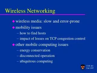
Wireless, mobility: impact on higher layer protocols • logically, impact should be minimal … • best effort service model remains unchanged • TCP and UDP can (and do) run over wireless, mobile • … but performance-wise: • packet loss/delay due to bit-errors (discarded packets, delays for link-layer retransmissions), and handoff • TCP interprets loss as congestion, will decrease congestion window un-necessarily • delay impairments for real-time traffic • limited bandwidth of wireless links