Download
1 / 35
350 likes | 562 Vues
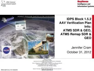
IDPS Block 1.5.2 AAV Verification Plan Info: ATMS SDR & GEO, ATMS Remap SDR & GEO. Jennifer Cram October 31, 2012. JPSS CGS Form J-110 10/22/2010. Objective/Agenda. Summarize the IDPS Algorithm Analysis Verification (AAV) Plan (approved by DPE and DPA at 7/10 and 8/10 meetings)

E N D
IDPS Block 1.5.2 AAV Verification Plan Info: ATMS SDR & GEO,ATMS Remap SDR & GEO Jennifer Cram October 31, 2012 JPSS CGS Form J-110 10/22/2010
Objective/Agenda • Summarize the IDPS Algorithm Analysis Verification (AAV) Plan (approved by DPE and DPA at 7/10 and 8/10 meetings) • Algorithm specific info on quality flag triggering • Algorithm specific info on IDPS QF verification plan
IDPS Block 1.5.2 Qual and AAV • IDPS Block 1.5.2 Qual • Functional requirements (ING, INF, PRO, DDS, DQM) • 301 PRO functional Block 1.5.2 Qual reqts - includes ExtG, Maneuver, Graceful Deg, Interfaces, EDRIR Alg Inputs and Outputs, etc. • 246 are Test-only (Test Procedures, detailed in IDPS Test Plan) • 55 involve Analysis. Detailed in Analysis/Inspection Plans (AIPs) and Analysis/Inspection Reports (AIRs) (SE-J-198A) • Test Data sets • Transitioning to OPS 17 day • Additional specific ops data sets being collected to support verification of specific IDPS requirements for Maneuver, Solar and Lunar Eclipse, etc. • AAV Block 1.5.2- Algorithm Analysis Verification • Verification event for unique PRO EDRPR quality requirements • Requirement Re-write – are 120 reqts (47 products) • Will be AIPs and AIRs for all of these • Use OAA Test Data sets • Carefully chosen test orbits/granules to replace proxy data for algorithm chain testing (May 15, 2012 focus day) • OAA Chain runs start from RDRs
IDPS EDRPR-related Requirement Verification – Past and Present • FPV – previous Block 1.0 • Verification was documented in SVRs • Verification had 3 parts • IPAC – Stand-alone and Chain comparisons to NG Truth data • Fill/Exclusion tests verified separately • Quality Flags • Proxy data sets plus 50+IDPS-altered non-nominal datasets • AAV – current Block 1.5.2 • Verification will be documented in AIPs and AIRs • Verification has 3 parts • Build-2-Build tests \(continue the baseline Pedigree from Block 1.0, SVRs, MX builds) • Exclusion/Fill Requirements verified separately • Quality Flags • OPS data sets plus minimal IDPS-altered non-nom granules (from OPS granules)
Block 1.5.2 IDPS PRO EDRPR-related (AAV) Requirements • For each SDR/EDR we have a set of 3 requirements • A(Basic EDRPR functionalities): The Processing SI shall generate the xxx xDR as specified in section x.y of the JPSS Environmental Data Record (EDR) Production Report for NPP, 474-00012 • B (EDRPR Fill exclusions) : The Processing SI shall provide fill values for the xxx xDR in accordance with section x.y of the JPSS Environmental Data Record (EDR) Production Report for NPP, 474-00012 • (cloudiness exclusions , sza exclusions, etc.) • C (EDRPR Quality Flags): The Processing SI shall generate the xxx xDR Quality Flags that are listed in Table 8-x of the JPSS Environmental Data Record (EDR) Production Report for NPP, 474-00012.
Approach for Verification of “A” (Basic Functionality) Reqts • Reqts with basic functionality per the EDR PR are verified by the pedigree of the B2B Quality testing • Unbroken pedigree on both the Development and Sustainment sides • Sustainment and Development B2B continuous testing • Additional testing for specific items as needed • Tests include • Specific Build-2-Build Statistical Comparisons (IDPS2IDPS) • Specific ”Calculated Truth” Comparisons (IDPS2IDPSTRUTH) • B2B Evaluation attempts to be as quantitative as practical • All comparisons, rationales documented • All artifacts CM’d • OAA B2B testing uses a standard set of IDPS Test data Granules • Transitioning from proxy to May 15 Ops set
Approach for Verification of “B” (Fill Exclusion) Reqts • Fill requirements for exclusions and missing data (cloud exclusions, sza excl, etc) that are in the EDR PR. • Includes Fill Values/Types from EDR PR as well as CDFCB Definitions of Fill Values (MISS, NA, ERR, and DNE fill cases) • Will run “calculated truth” tests that fill values and associated Quality Flags are correct. • Most of these are done in build-to-build IDPS regression tests if granules trigger these behaviors • Will explicitly be analyzed in final AAV verification (AIR) • Test done in appropriate granules for the product (cloudiness, sza threshold, etc.)
Approach for Verification of “C” (Quality Flag) Reqts • Quality Flag Testing • New QF’s • verified in Path C PCR S-AIRs – formal process, reviewed by NASA • Included in B2B testing from that point forward, • B2B Quality Testing: • IDPS B2B testing analyzes differences, rationale • Verifies most quality Flag's that are triggered in the B2B Test Data Granules • Non-nominal tests for specific Quality Flag's that are not triggered in the B2B Test data Granules • Limited specially-created non-nom datasets - ~ 5 separate datasets instead of the 50+ currently in use. • Limited captured special conditions datasets - (Solar, lunar eclipse, Maneuver, others) • These datasets will not trigger every single Quality Flag, but will trigger many of the most used and most important QFs • A few qf’s are not triggered at all in the nominal Test Data Granules or the NN datasets – IDPS believes that these were sufficiently verified in SVRs and do not need special datasets/runs. Identified in xls. • Detailed xls has all the info on which QF’s are verified by B2B, which require more analysis for AAV, which are not specifically verified in AAV.
QF xls - Summary • QF xls was reviewed/discussed in the July 10 and Aug 10 mtgs • xls is intended to list all of the EDRPR Quality flags and to summarize the category of the planned IDPS verification for each quality flag. • How each of the quality flags was verified in the past FPV event • Whether the quality flags are triggered in the IDPS Test data sets • How IDPS/PRO is planning to verify each quality flag for AAV • The EDRPR quality flags are covered under specific Block 1.5.2 AAV IDPS/PRO requirements (under revision, 1 QF reqt per product) • Analysis Inspection Plan (AIP) is written to outline the proposed verification; the AIPs go through the critique and ECR process • Analysis Inspection Report (AIR) is written with the results, consistent with the approved AIP. The AIR also undergoes a critique and ECR process. • This is the current IDPS Plan – can be discussed, modified. But still have to balance completeness, schedule, and risk
VIIRS QF Verification: VIIRS CDCNN Datasets • Carefully Designed Catastrophic Non-Nominal (CDCNN) Dataset • Careful design to remove specific VIIRS EV, Cal, and Eng/Thermal packets through a single granule to trigger as many fill and qf conditions as possible throughout the chain (xls shows a rough idea of algs/qf’s that will be affected). • Example: • M15-Band EV missing affects SDR, Imagery EDR, IST EDR, LST EDR, SST EDR • I1-Band EV missing affects SDR, Imagery EDR, SIC EDR. Snow EDRs, VI EDR • M5 Cal packet missing affects SDR qf’s, downstream cloud EDR qf’s • CDCNN usage allows efficient way to run, trigger, analyze a lot of non-nominal VIIRS behavior • CDCNN datasets will be designed for 1 tropical and 1 polar granule • Each dataset will likely have ~15 EV packet removals (15 different bands ), ~5 Cal packet removals (5 different bands), ~1 Eng packet removal. Specific scans and detectors will be carefully chosen for every packet removal in a granule dependent upon the actual scenario (ocean, land, ice, snow) and cloud cover in that granule. • Share/Use these datasets Internally and Externally
Objective/Agenda • Summarize the IDPS Algorithm Analysis Verification (AAV) Plan (approved by DPE and DPE at 7/10 and 8/10 meetings) • Algorithm specific info on quality flag triggering • Algorithm specific info on IDPS QF verification plan
Granule level QF’s – General Info • Most granule level summary qf’s are percentages: • Denominator is number of pixels that are not DNE or pixel trim • Numerator is number of pixels (per denom) triggered in a pixel-level qf. • Out of range summary qf’s have numerator and denominator only calculated over non-fill pixels • Exclusions Summary qf’s are per NG-specified specific definitions – (usually) includes all performance and production exclusions (i.e. exclusions where not produced as well as exclusions where produced but under conditions that are not supposed to count towards performance reqts (in original NPOESS Sys Spec).
ATMS Info • ATMS SDR • Granule is 12 scans, 22 channels, 96 beam positions • ATMS SDR GEO – 12 scans , 96 beam positions • ATMS Remap is a remap of the ATMS SDR to the CrISGeolocation • Time is actually used for the remap (not Lat/lon • When the CrIS GEO is missing (Cris SDR was not created for some reason) then a “fake Cris GEO” is created in the code by assuming nadir pointing • 4 scans x 30 FOR • ATMS Remap GEO
ATMS SDR QF’s • Granule-level • Summary ATMS SDR Quality • Health and Status • Quadratic Correction
ATMS SDR QF’s • Scan-level • Time sequence error • Data Gap • KAV PRT Conversion error • WG PRT Conversion error • Space View antenna position error • Blackbody antenna position error • Moon in Space View • Gain Error • Shelf PRT Conversion Error • KAV PRT Temperature Limits Check • WG PRT Temperature Limits Check • KAV PRT Temperature Consistency Check • WG PRT Temperature Consistency Check • KAV PRT Temperature Data Sufficiency Check • WG PRT Temperature Data Sufficiency Check • Space View Count Limits Check • Blackbody Count Limits Check • Space View Count Consistency Check • Blackbody Count Consistency Check • Space View Data Sufficiency Check • Blackbody Data Sufficiency Check • Calibration with Fewer Than Preferred Samples
ATMS Remap and GEO QF’s • ATMS Remap SDR QF’s • Granule -level • Sync Error • FOR-level • Resampled Footprint Quality • ATMS Remap GEO QF’s • Missing ephem • ATMS SDR GEO QF’s • Missing ephem
ATMS SDR Granule-level QF Info • Summary ATMS SDR Quality • This is a Metadata “Granule-level” QF, it represents the percentage of good quality retrievals in the granule. It ranges from 0 to 100. • The QF is defined as: • A poor retrieval is defined as a retrieval that is: • Retrieval w/ FILL, OR • "Moon in Space View" QF (1 bit per channel/scan) for that retrieval is set, OR • “Calibration with Fewer Than Preferred Samples” QF (1 bit per channel/scan) for that retrieval is set • Total Number of Retrievals is defined as: • Total Number of Scans per Granule (nominal is 12 or 11 for short granule) x Total Number of Channels (22) x Total Number of Earth View Samples (96)
ATMS SDR Granule-level QF Info • Health and Status • A H&S QF bit is triggered when the corresponding WORD (2 bytes) in the ATMS Health & Status Engineering AP (APID 531) is “out of range”. A WORD in APID 531 is out of range when its value falls outside the corresponding lower/upper limits obtained from the ATMS SDR Ephemeral Processing Configuration Parameter file • Quadratic Correction • This flag is set when quadratic correction is applied to the radiometric transfer function for non-linearity correction • Quadratic correction is controlled through the “useQuadraticTerm” logical in the ATMS SDR Ephemeral Processing Coefficient file. If that logical is set to “TRUE” then quadratic correction is applied, otherwise it’s not. • Quadratic correction can be applied through two mechanisms which is controlled by the setting of the “useQuadraticTele” logical in the ATMS SDR Ephemeral Processing Coefficient file. I • f the logical “useQuadraticTele” is set to “FALSE”, then quadratic correction coefficients are obtained from the ATMS SDR Ephemeral Processing Coefficient file • If the logical “useQuadraticTele” is set to “TRUE”, then quadratic correction coefficients are obtained from the ATMS CAL APID 515
ATMS SDR Scan-level QF’s • Time sequence error • Triggered when the time difference b/n the start time of current scan and the start time of the previous scan is: • Less than (8/3 (sec) – allowableDev (sec)) OR • Greater than (8/3 (sec) + allowableDev (sec)) • The parameter allowableDev is set to 18 msec in the ATMS SDR Ephemeral Processing Coefficient file. This QF is 1 bit/scan (1st bit in QF19_SCAN_ATMSSDR). • Data Gap • If there is a data gap, i.e., missing scan(s) preceding the current scan, then this flag (2nd bit in QF19_SCAN_ATMSSDR Byte) is set.
ATMS SDR Scan-level QF’s • KAV PRT Conversion error • If divide-by-zero condition exits, or if computation loop fails to converge in the temperature computations for the 8 KAV (K/Ka and V Band) PRTs, the condition is flagged by the corresponding bit (for that failed PRT) in the flag QF12_SCAN_KAVPRTCONVERR Byte to indicate which PRT(s) has failed. • WG PRT Conversion error • If divide-by-zero condition exits, or if computation loop fails to converge in the temperature computations for the 7 WG Band PRTs, the condition is flagged by the corresponding bit (for that failed PRT) in the flag QF13_SCAN_WGPRTCONVERR Byte to indicate which PRT(s) has failed
ATMS SDR Scan-level QF’s • Space View antenna position error • There are 4 space view antenna groupings. ATMS is commanded to use one of the 4 groupings. The grouping selected is indicated by the Scan Pattern ID, bits 7-9 in the INSTRUMNET_MODE (Word 73) in the Health and Status packet APID 531. Values are interpreted as: 001, 010, 011, 100 = RAM profiles 1, 2, 3, 4. The expected resolver counts for the 4 space view positions are listed in the table below: • If any of the actual space view position (as determined from the scan angle counts in the Science Data packet) does not fall within the range of the expected count +/- εc, the Space View Antenna Position Error flag is set. The expected counts in the above table and εc are tunable parameters in the ATMS SDR Ephemeral Processing Coefficient file
ATMS SDR Scan-level QF’s • Blackbody antenna position error • There are 4 blackbody view positions. The expected resolver counts listed in the table below are the same for all 4 scan profiles: • If any of the actual blackbody view position (as determined from the scan angle counts in the Science Data packet) does not fall within the range of the expected count +/- εw, the Blackbody Antenna Position Error flag is set. The expected counts in the above table and εw are tunable parameters in the ATMS SDR Ephemeral Processing Coefficient file • Moon in Space View • Gain Error • Shelf PRT Conversion Error • KAV PRT Temperature Limits Check • WG PRT Temperature Limits Check • KAV PRT Temperature Consistency Check • WG PRT Temperature Consistency Check • KAV PRT Temperature Data Sufficiency Check • WG PRT Temperature Data Sufficiency Check • Space View Count Limits Check • Blackbody Count Limits Check • Space View Count Consistency Check • Blackbody Count Consistency Check • Space View Data Sufficiency Check • Blackbody Data Sufficiency Check • Calibration with Fewer Than Preferred Samples
ATMS SDR Scan-level QF’s • Moon in Space View • If the Moon appears in any of the four calibration space views, then this flag (1st bit in QF20_ATMSSDR Byte) is set. The flag is 1 bit/channel/scan. • Theoretical background: The cold space view temperature increase caused by the lunar contamination is given as: • Where: • β : nominal area ration of moon to FOV Tmoon : effective moon temperature [K] θ: separation angle between moon and sun (θ=180o in case of Full Moon) Finally, the cold space view temperature increase caused by the lunar contamination is calculated. If the lunar intrusion temperature increase (ΔTc) is larger than the threshold (ΔT0) for the given channel, then the cold space view count is set to a fill value (NA_INT32_FILL) in the verified RDR and the Moon In Space View Quality Flag is set for this scan and channel. The ΔT0 values are implemented as tunable parameters in the ATMS SDR Ephemeral Processing Coefficients file. For now, all values are set to 0.2 K. • Gain Error • Shelf PRT Conversion Error • KAV PRT Temperature Limits Check • WG PRT Temperature Limits Check • KAV PRT Temperature Consistency Check • WG PRT Temperature Consistency Check • KAV PRT Temperature Data Sufficiency Check • WG PRT Temperature Data Sufficiency Check • Space View Count Limits Check • Blackbody Count Limits Check • Space View Count Consistency Check • Blackbody Count Consistency Check • Space View Data Sufficiency Check • Blackbody Data Sufficiency Check • Calibration with Fewer Than Preferred Samples
ATMS SDR Scan-level QF’s • Gain Error • If the lowest blackbody count is smaller than or equal to the highest space view count in a scan, the condition is flagged (2nd bit in QF20_ATMSSDR Byte). This flag is 1 bit/channel/scan. • Shelf PRT Conversion Error • If divide-by-zero condition exits, or if computation loop fails to converge in the temperature computations for the 4 Receiver Shelf (K/Ka, V, W and G) PRTs, the condition is flagged by the corresponding bit (for that failed PRT) in the flag QF14_SCAN_SHELFPRTCONVERR Byte to indicate which PRT(s) has failed. This flag is 4 bits/scan. • KAV PRT Temperature Limits Check • Each of the 8 KAV PRT temperatures is checked against a lower limit and an upper limit. Out of range condition is flagged by the corresponding bit (for that failed PRT) in the flag QF15_SCAN_KAVPRTTEMPLIMIT Byte to indicate which PRT(s) has failed the test.
ATMS SDR Scan-level QF’s • WG PRT Temperature Limits Check • Each of the 7 WG PRT temperatures is checked against a lower limit and an upper limit. Out of range condition shall be flagged by the corresponding bit (for that failed PRT) in the flag QF16_SCAN_WGPRTTEMPLIMIT Byte to indicate which PRT(s) has failed the test. • KAV PRT Temperature Consistency Check • The 8 KAV PRT temperatures are checked against each other for consistency. The check failure is flagged by the corresponding bit (for that failed PRT) in the flag QF17_SCAN_KAVPRTTEMPCONSISTENCY Byte to indicate which PRT(s) has failed the test. • WG PRT Temperature Consistency Check • The 7 WG PRT temperatures are checked against each other for consistency. The check failure is flagged by the corresponding bit (for that failed PRT) in the flag QF18_SCAN_WGPRTTEMPCONSISTENCY Byte to indicate which PRT(s) has failed the test.
ATMS SDR Scan-level QF’s • KAV PRT Temperature Data Sufficiency Check • If insufficient KAV PRT data are available, either because of missing data or failing to pass the quality checks, then this flag (3rd bit in QF19_SCAN_ATMSSDR Byte) is set. • WG PRT Temperature Data Sufficiency Check • If insufficient WG PRT data are available, either because of missing data or failing to pass the quality checks, then this flag (4th bit in QF19_SCAN_ATMSSDR Byte) is set. • Space View Count Limits Check • Each of the 4 space view counts for each channel is checked against a lower limit and an upper limit. Out of range condition is flagged by the corresponding bit (for that failed SV) in the flag QF21_ATMSSDR Byte (1st 4 bits in that Byte) to indicate which sample(s) has failed the test.
ATMS SDR Scan-level QF’s • Blackbody Count Limits Check • Each of the 4 blackbody counts for each channel is checked against a lower limit and an upper limit. Out of range condition is flagged by the corresponding bit (for that failed BB) in the flag QF21_ATMSSDR Byte (last 4 bits in that Byte) to indicate which sample(s) has failed the test. • Space View Count Consistency Check • The 4 space view counts are checked against each other for consistency. The check failure is flagged by the corresponding bit (for that failed SV) in the flag QF22_ATMSSDR Byte (1st 4 bits in that Byte) to indicate which sample(s) has failed the test. • Blackbody Count Consistency Check • The 4 blackbody counts are checked against each other for consistency. The check failure is flagged by the corresponding bit (for that failed BB) in the flag QF22_ATMSSDR Byte (last 4 bits in that Byte) to indicate which sample(s) has failed the test.
ATMS SDR Scan-level QF’s • Space View Data Sufficiency Check • If insufficient space view samples are available, either because of missing data or failing to pass the quality checks, this flag (4th bit in QF20_ATMSSDR Byte) is set. • Blackbody Data Sufficiency Check • If insufficient blackbody samples are available, either because of missing data or failing to pass the quality checks, this flag (5th bit in QF20_ATMSSDR Byte) is set. • Calibration with Fewer Than Preferred Samples • Multiple scans and samples are used for averaging the blackbody PRT temperatures, the blackbody counts and the space view counts. If the scan line is calibrated with fewer than the preferred number of samples and/or scans either because of missing data or some data failing the quality checks, this flag (3rd bit in QF20_ATMSSDR Byte) is set.
ATMS SDR GEO and ATMS Remap GEO QF’s • Both SDRs GEO has a missing ephemeris qf • Missing Ephemeris or Attitude Data • S/C Diary RDR Data (20 sec granules, 1 packet/sec) • CGS also has daily TLE, SGP4 propagation • QF Options • Nominal • Small Gap (<= 30 secs) • Ephemeris and attitude interpolated between ends • Large Gap (greater than small gap) or overlaps Granule Boundary • Ephemeris uses prediction from TLE, interpolation between prediction and S/C diary ephemeris. • Attitude assumed perfect nadir • Missing for Entire granule (Uses Prediction from TLE) • Ephemeris uses prediction from TLE • Attitude assumed perfect nadir
ATMS Remap QF’s • Sync Error • The ATMS REMAP Synch Error QF, QF4_ATMSREMAPSDR bit 1, is a scan level QF. For each CrIS scan i, the ATMS Remap algorithm attempts to locate a synchronized ATMS SDR scan out of a grouping of ATMS granules i-1, i, and i+1. An ATMS granule contains 12 scans, while a CrIS granule contains 4 scans. Therefore, for CrIS granule i, ATMS REMAP algorithm searches 36 ATMS scans for a match. An ATMS scan is determined to be synched with a CrIS scan if the time difference between the mid times of the 47th ATMS beam position and the 15th CrIS FOR is within the delta time specified by a tunable parameter. If a synched ATMS scan cannot be found for a CrIS scan, the synch error QF is set for that Remap scan. • The ATMS REMAP algorithm is hard-coded to use the ATMS beam position 47 mid time and the CrIS FOR 15 mid time for synchronization, which is the middle of the scan. This assumes that the ATMS and CrIS sensors are synched in the middle of a scan as they are in proxy data. A tunable parameter in ATMS-REMAP-SDR-CC, expTimeDiff, may be used to account for the sensors being synched elsewhere without changing the code. Operationally, the sensors are synched at the edge of scan and expTimeDiff is the expected time difference between an edge of scan synch and a middle of scan synch. • Another tunable parameter in ATMS-REMAP-SDR-CC is synchDeltaMax which defines the maximum allowable deviation from the ideal time difference. Therefore, a CrIS scan is synched to an ATMS scan when the following condition is true: (ATMS 47th beam position mid time) – (CrIS 15th FOR mid time)– expTimeDiff <= synchDeltaMax
ATMS Remap QF’s • Resampled Footprint Quality • ATMS Remap Resampled Footprint Quality is a pixel-level QF which is produced for each channel. This QF is set when any of the ATMS SDR brightness temperatures that are used to derive the ATMS Remap brightness temperature for a particular FOR are set to fill. • For a CrIS granule i, Remap groups together 36 ATMS SDR scans from granules i-1, i, and i+1. For each CrIS scan in granule i, Remap finds the ATMS scan whose 47th beam position time is within a configurable delta of the CrIS SDR 15th FOR time. Once an ATMS scan is matched, the Remap algorithm determines a brightness temperature for each FOR in the scan by using ATMS-FPMATCH-LUT to determine which ATMS SDR brightness temperatures to resample. • The ATMS-FPMATCH-LUT contains the following information: • Number of samples to use for each FOR (numResBeamPos; a function of FOR and ATMS channel); • A scan offset for each sample (trackOff; a function of the FOR, ATMS channel, and the sample number); and • The ATMS SDR beam position (scanPos; also a function of the FOR, ATMS channel, and the sample number) for each sample. • The Resampled Footprint Quality QF is set if any of the sampled brightness temperatures contain fill.
Objective/Agenda • Summarize the IDPS Algorithm Analysis Verification (AAV) Plan (approved by DPE and DPE at 7/10 and 8/10 meetings) • Algorithm specific info on quality flag triggering • Algorithm specific info on IDPS QF verification plan
ATMS SDRs QF Verification • Review QF xls: • ATMS SDR QF’s • ATMS SDR GEO QF’s • ATMS Remap SDR QF’s • ATMS Remap SDR GEO QF’s
References • FPV SVRs –Erooms at Ground Data Product Engineering > IDPS SVRs • IDPS AAV Info – Erooms at Ground Data Product Engineering > IDPS AAV Verification