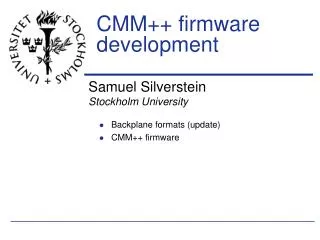
CMM++ firmware development
CMM++ firmware development. Samuel Silverstein Stockholm University. Backplane formats (update) CMM++ firmware. CMM++ firmware. Questions: How much work to produce initial firmware for the CMM++? Can a "Day-1" compatible CMM++ be implemented in the target Virtex-6?

CMM++ firmware development
E N D
Presentation Transcript
CMM++ firmware development Samuel Silverstein Stockholm University • Backplane formats (update) • CMM++ firmware
CMM++ firmware • Questions: • How much work to produce initial firmware for the CMM++? • Can a "Day-1" compatible CMM++ be implemented in the target Virtex-6? • Implications for CMM++ hardware? • Idea: Adapt "Day-1" Jet CMM f/w to Virtex-6 • Existing VHDL with minimal changes • Same development environment (Mentor/ISE) • Set realistic user constraints (UCF)
CMM++ concept (Yuri) VME-- Glink Legacy DAQ and ROI readout Glink Input from JEM/CPM 12-fiber bundles, 6.4/10 Gbit/s/fiber Tx and/or Rx SNAP12 Virtex 6 HX565T LVDS merger links SNAP12 SNAP12 Not a complete picture! SNAP12 Legacy LVDS outputs to CTP SNAP12 Input from JEM/CPM modules (160 MHz) SNAP12 3
The current CMM VME-- VME CPLD Glink DAQ and ROI readout TTCrx Glink Input from JEM/CPM LVDS merger links Virtex E (crate) Virtex E (system) Input from JEM/CPM modules (40 MHz) LVDS outputs to CTP 4
"Day-1" firmware, first try: VME-- VME CPLD Glink DAQ and ROI readout TTCrx Glink Input from JEM/CPM Implement in Virtex 6 (XC6VHX565T-2FF1924) from existing VHDL LVDS merger links Virtex E (crate) Virtex E (system) Input from JEM/CPM modules (40 MHz) LVDS outputs to CTP 5
Firmware is easy to port • Top-level VHDL design, containing both crate and system FPGAs plus interconnects (done) • Most of code pure VHDL, ports transparently • Two architecture-specific changes • Block RAMs 4k 18k or 36k (Done 1 1) • Clocking: DLLs MMCM • Advanced mixed-mode clock manager (Done) • Note: UNISIM libraries for Mentor compatibility
Results from first attempt • Note: numbers come from Precision, not ISE • Take as an early, rough estimate • Plenty of resources left in FPGA • Logic slices: about 2% used • Registers: about 2% used • Block RAM: about 5% • Can be reduced by at least 1/2 by more efficient use of 18kb and 36 kb memories. • Significantly faster than Virtex-E • Max. frequency more than 120 MHz without trying • Can save several ticks of latency • I/O requirements very close to limit...
I/O budget for V6HXT565 • Available I/O (not including transceivers): 640 pins • Real-time data path: • Backplane input (16 x 25): 400 • Cables (3 x 25): +75 • CTP output (2 x 33): +66 = 541 pins • Control and timing: • VME-- from CPLD 35 • TTC (L1A, BCR, deskew 1 and 2) +4 • Crystal clock +1 • clr_pe,rst,rst_dll,pbk_en,can_mc,en_cblout +6 = 46 pins • Readout: • Glink data outputs 2 x 20 40 • DAV pins 2 = 42 pins • Indicator LEDs : 8 + 8 pins • TOTAL: 637 / 640637 • This is after removing spare TTL and test ports.
637/640 is too many • I/O banks include multi-function pins: • VREF • Global clock inputs • So we can't use all of the pins just for I/O
Can we save I/O? • Available I/O (not including transceivers): 640 pins • Real-time data path: • Backplane input (16 x 25): 400 • Cables (3 x 25): +75 • CTP output (2 x 33): +66 = 541 pins • Control and timing: • VME-- from CPLD 35 • TTC (L1A, BCR, deskew 1 and 2) +4 • Crystal clock +1 • clr_pe,rst,rst_dll,pbk_en,can_mc,en_cblout +6 = 46 pins • Readout: • Glink data outputs 2 x 20 40 • DAV pins 2 = 42 pins • Indicator LEDs : 8 + 8 pins • TOTAL: 637 / 640 637. • <600 Move to FPGA from CPLD Implement Glink in Virtex 6?
Glink in Virtex 6: • Glink emulation already done in other FPGAs • Altera provided code for Stratix GL • Has been ported to Xilinx FPGAs • Virtex 4, Virtex 5 • L1Muon collaborators at INFN most recently ported to Virtex 5, with both simple and enhanced modes • Shared code, documentation to me • Seems straightforward to adapt to Virtex 6
"Day-1" firmware, next try: VME-- VME CPLD Glink DAQ and ROI readout TTCrx Glink Input from JEM/CPM LVDS merger links Virtex E (crate) Virtex E (system) Input from JEM/CPM modules (40 MHz) LVDS outputs to CTP 12
Next steps... • Add Glink functionality in two GTX tx • Produce "realistic" user constraint file (UCF) • All I/Os arranged in appropriate banks • Correct signal levels for backplane, cables, CTP, etc... • Differential global clock inputs • etc... • Implement in ISE to check actual resource use, clock speed • Simulate to verify correct behavior
Looking even further("stage 2") • Add block for receiving and distributing 160 MHz backplane signals • Add multi-Gbit tranceivers to serialize and send out backplane data over fibers • Do similar for non-system-merging CMM++
CMM++ "stage 2" VME-- Glink I N P U T Input from JEM/CPM Glink 8b/10b ser LVDS merger links SNAP12 Crate SYS to CTP Input from JEM/CPM modules (160 MHz) 15
Backplane formats CPM: JEM:
Thoughts / conclusions • Straightforward to port existing CMM VHDL code to Virtex 6 • FPGA-specific elements using Unisim • I/O is a limiting factor, seems to point towards a favored architecture • External CPLD for VME interface • G-link readout emulated with GTX transmitters • Early CMM++ staging possible by adding more components to "Day-1" design • Don't need to start each new stage from scratch! • No show stoppers so far!