Download
1 / 11
110 likes | 195 Vues
https://gioumeh.com/product/structural-and-stress-analysis-solution/<br>-------------------------------------------------------------------<br>Authors: T.H.G. Megson<br> Published: Elsevier 2005 | Elsevier 2019<br> Edition: 2nd | 4th<br> Pages: 266 | 455<br> Type: pdf<br> Size: 1MB |5.36MB

E N D
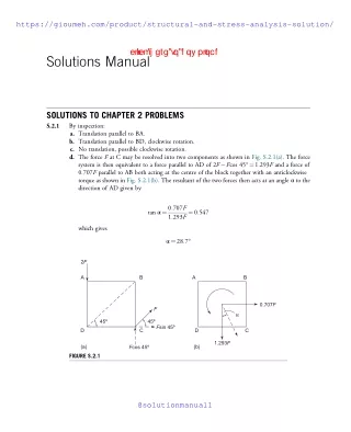
https://gioumeh.com/product/structural-and-stress-analysis-solution/https://gioumeh.com/product/structural-and-stress-analysis-solution/ cl i ck h ere t o d ow nl oad Solutions Manual SOLUTIONS TO CHAPTER 2 PROBLEMS S.2.1 By inspection: a. Translation parallel to BA. b. Translation parallel to BD, clockwise rotation. c. No translation, possible clockwise rotation. d. The force F at C may be resolved into two components as shown in Fig. S.2.1(a). The force system is then equivalent to a force parallel to AD of 2F?Fcos 45°¼1.293F and a force of 0.707F parallel to AB both acting at the centre of the block together with an anticlockwise torque as shown in Fig. S.2.1(b). The resultant of the two forces then acts at an angle α to the direction of AD given by tan α¼0:707F 1:293F¼0:547 which gives α¼28:7° 2F A B A B 0.707F F α 45º 45º Fsin 45º D C D C 1.293F (a) (b) Fcos 45º FIGURE S.2.1 @solutionmanual1
dumperina e2 Solutions Manual https://gioumeh.com/product/structural-and-stress-analysis-solution/ S.2.2 a. Vectors representing the 10 and 15 kN forces are drawn to a suitable scale as shown in Fig. S.2.2. Parallel vectors AC and BC are then drawn to intersect at C. The resultant is the vector OC which is 21.8 kN at an angle of 23.4° to the 15 kN force. cl i ck h ere t o d ow nl oad B C 10kN R 60° q O 15kN A FIGURE S.2.2 b. From Eq. (2.1) and Fig. S.2.2 R2¼152þ102þ2?15?10cos 60° which gives R ¼21:8kN Also, from Eq. (2.2) 10sin 60° 15þ10cos 60° tan θ¼ so that θ¼23:4°: S.2.3 a. Thevectorsdonothavetobedrawninanyparticularorder.Fig.S.2.3showsthevectordiagram with the vector representing the 10 kN force drawn first. The resultants R is then equal to 8.6 kN and makes an angle of 23.9° to the negative direction of the 10 kN force. b. Resolving forces in the positive x direction Fx¼10þ8cos 60°?12cos 30°?20cos 55°¼?7:9kN Then, resolving forces in the positive y direction Fy¼8cos 30°þ12cos 60°?20cos 35°¼?3:5kN The resultant R is given by R2¼ð?7:9Þ2þð?3:5Þ2 @solutionmanual1
e3 Solutions to Chapter 2 Problems https://gioumeh.com/product/structural-and-stress-analysis-solution/ 12kN cl i ck h ere t o d ow nl oad 8kN q 10kN R 20kN FIGURE S.2.3 so that R ¼8:6kN Also tan θ¼3:5 7:9 which gives θ¼23:9°: S.2.4 SincethejointsatA,B,andCarehingedandtheloadisappliedatjointB,theforcesinABandBC will be purely axial. Assume that the force in AB is tension and in BC is compression (if a wrong assumption is made the answer will be negative). 1.5 m FAB A B 10 kN 3 m FCB α C FIGURE S.2.4(a) @solutionmanual1
e4 Solutions Manual https://gioumeh.com/product/structural-and-stress-analysis-solution/ Referring to Fig. S.2.4(a), the hinge at B is in equilibrium under the action of the horizontal force FAB, the inclined force FCB, and the 10 kN load. Also cl i ck h ere t o d ow nl oad α¼ tan?11:5 3¼26:6 Resolving forces vertically at B FCBcos 26:6°?10¼0, which gives FCB¼11:26kN compression ð Þ Now resolving forces horizontally at B FAB?FCBsin 26:6°¼0 from which FAB¼5:0kN tension ð Þ Alternatively, FABcan be found by resolving forces at B in a direction perpendicular to CB, i.e. FABcos 26:6°?10 sin 26:6°¼0, which again gives FAB¼5:0kN tension ð Þ Since the hinge at B is in equilibrium under the action of the three forces acting at B, it may be represented by a triangle of forces as shown in Fig. S.2.4(b), which is constructed as d 26.6° 11.2 kN 10 kN f e 5.0 kN FIGURE S.2.4(b) @solutionmanual1
e5 Solutions to Chapter 2 Problems https://gioumeh.com/product/structural-and-stress-analysis-solution/ follows. Draw to a suitable scale the vector df vertically downwards to represent the 10 kN load. Then draw fe and ed parallel to AB and CB, respectively. The point of intersection e completes the triangle of forces. The vector fe represents the force FABin magnitude and direction, while the vector ed represents the force FCBin magnitude and direction. Note that the direction of the forces as depicted by the arrows in Fig. S.2.4(b) is their action on the hinge at B. cl i ck h ere t o d ow nl oad S.2.5 Label the spaces between the forces as shown in Fig. S.2.5(a). Note that the reaction at the support B has been previously calculated. Draw cd to represent the 5 kN load downwards and to the right parallel to the load. Then draw de to the same scale to represent the 10 kN load upwards and to the right. Now draw ef, fg, and gh to represent the 0.7 kN reaction at B, the downward 2 kN load, and the 3 kN load, respectively. The force diagram is completed by the vector hc, which represents the reaction at A in magnitude and direction as shown in Fig. S.2.5(b). D 5 kN 10 kN C E H G F RA RB = 0.7 kN 3 kN 2 kN (a) FIGURE S.2.5(a) e f g RA = 9.6 kN c h 10.8° d (b) FIGURE S.2.5(b) S.2.6 Referring to Fig. S.2.6 the resultant, R, of the force system is given by R ¼5þ4?8þ10¼11kN @solutionmanual1
e6 Solutions Manual https://gioumeh.com/product/structural-and-stress-analysis-solution/ cl i ck h ere t o d ow nl oad a y 5 kN R 4 kN 10 kN 30° (0,1.0) 8 kN x 1.0 m 0.75 m 0.5 m FIGURE S.2.6(a) Then Rx¼11 cos 60°¼5:5kN, Now taking moments about the line of action of the 5 kN force Ry¼11 sin 60°¼9:5kN: Ra¼4?1?8?6:5þ10?225¼11a from which a¼1:32m: 1.32 m y 5 kN R (0,1.0) a b c 60° x e d f FIGURE S.2.6(b) @solutionmanual1
e7 Solutions to Chapter 2 Problems https://gioumeh.com/product/structural-and-stress-analysis-solution/ In Fig. S.2.6(b) the resultant, R, of the force system crosses the x axis at the point e. Then fe ¼ fd ? ed. Also fd ¼ bc ¼ 1.32 cos 30° ¼ 1.14 m and ed ¼ cd tan 30° ¼ bf tan 30° ¼ (af ? ab) tan 30° ¼ (1 ? 1.32 sin 30°) tan 30° ¼ 0.2 m. Therefore, fe ¼ 1.14 ? 0.2 ¼ 0.94 m. Referring to Fig. S.2.7 the resultant vertical force FVis given by cl i ck h ere t o d ow nl oad S.2.7 FV¼10þ8þ3¼21kN Taking moments about the centre of the cylinder FVx ¼10?1:25þ8?0:75?3?1:0 so that 21x ¼15:5 x– 10kN 8kN 3kN FV 0.5m 0.75m 1.0m FIGURE S.2.7 which gives x ¼0:738m The force system is then equivalent to a vertically downward force of 21 kN acting through the centre of the cylinder together with a torque T¼21?0.738¼15.5 kNm (anticlockwise). Alternatively, and more directly T ¼10?1:25þ8?0:75?3?1:0¼15:5kNmðanticlockwiseÞ The bending moment at the built in end is given by M ¼21?2:5¼52:5kNm S.2.8 Referring to Fig. S.2.7, the total vertical downward load on the end of the cantilever is given by @solutionmanual1 V¼10þ8þ3¼21kN F
e8 Solutions Manual https://gioumeh.com/product/structural-and-stress-analysis-solution/ The line of action has already been calculated in S.2.7 and is a distance of 0.738 m from the centre of the cylinder cross section. Therefore, the loading system may be replaced by an anticlockwise torque given by cl i ck h ere t o d ow nl oad T ¼21?0:738¼15:5kNm together with a vertically downward load of 21 kN acting through the cylinder cross section as shown in Fig. S.2.8. Torque = 15.5 kNm 21 kN FIGURE S.2.8 S.2.9 Initially the forces are resolved into vertical and horizontal components as shown in Fig. S.2.9. Then Rx¼69:3þ35:4?20:0¼84:7kN Now taking moments about the x axis Rxy¼35:4?0:5?20:0?1:25þ69:3?1:6 which gives y¼1:22m Also, from Fig. S.2.9 Ry¼60þ40þ34:6?35:4¼99:2kN Now taking moments about the y axis Ryx ¼40:0?1:0þ60:0?1:25?34:6?1:0 so that x ¼0:81m @solutionmanual1
e9 Solutions to Chapter 2 Problems https://gioumeh.com/product/structural-and-stress-analysis-solution/ y (1.0, 1.6) cl i ck h ere t o d ow nl oad x 69.3kN 30° 80kN 40kN ( 1, 1.25) 20.0kN Rx 50kN 30° 35.4kN 34.6kN 40kN 45° y (0, 0.5) 35.4kN Ry (1.25, 0.25) x O 60kN FIGURE S.2.9 The resultant R is then given by R2¼99:22þ84:72 from which R ¼130:4kN Finally θ¼tan?199:2 84:7¼49:5°: S.2.10 a. In Fig. S.2.10(a) the inclined loads have been resolved into vertical and horizontal components. The vertical loads will generate vertical reactions at the supports A and B while the horizontal components of the loads will produce a horizontal reaction at A only since B is a roller support. 3kN 7kN 8kN 6.1 kN 5.7 kN 60° 45° A B RA,H 3.5 kN 5.7kN RA,V RB,V 4 m 6 m 5 m 5 m FIGURE S.2.10(a) Taking moments about B RA,V?20?3?16?6:1?10?5:7?5¼0 @solutionmanual1
e10 Solutions Manual https://gioumeh.com/product/structural-and-stress-analysis-solution/ which gives cl i ck h ere t o d ow nl oad RA,V¼6:9kN Now resolving vertically RB,VþRA,V?3?6:1?5:7¼0 so that RB,V¼7:9 kN Finally, resolving horizontally RA,H?3:5?5:7¼0 so that RA,H¼9:2kN Note that all reactions are positive in sign so that their directions are those indicated in Fig. S.2.10(a). b. The loads on the cantilever beam will produce a vertical reaction and a moment reaction at A as shown in Fig. S.2.10(b). 5kNm MA A B 15kN RA 10m FIGURE S.2.10(b) Resolving vertically RA?15?5?10¼0 which gives RA¼65kN Taking moments about A MA?15?10?5?10?5¼0 from which MA¼400kNm Again the signs of the reactions are positive so that they are in the directions shown. c. In Fig. S.2.10(c) there are horizontal and vertical reactions at A and a vertical reaction at B. By inspection (or by resolving horizontally) @solutionmanual1 RA,H¼20kN
e11 Solutions to Chapter 2 Problems https://gioumeh.com/product/structural-and-stress-analysis-solution/ 20kN cl i ck h ere t o d ow nl oad 5m 10kN 15kN 5kN/m A RA,H B RA,V RB 2m 4m 2m 2m FIGURE S.2.10(c) Taking moments about A RB?8þ20?5?5?2?9?15?6?10?2¼0 which gives RB¼12:5kN Finally, resolving vertically RA,VþRB?10?15?5?2¼0 so that RA,V¼22:5kN: d. The loading on the beam will produce vertical reactions only at the supports as shown in Fig. S.2.10(d). 75kN/m 8kN/m A B RB RA 3m 9m FIGURE S.2.10(d) Taking moments about B RA?12þ75?8?12?6¼0 Hence RA¼41:8kN @solutionmanual1