Download
1 / 24
240 likes | 263 Vues
Explore the evolution of Undulator Vacuum Chamber Design with prototype updates, welding challenges, and bellows module integration. Learn about polishing processes and risk mitigation strategies for chamber construction. Scheduled for completion in 2004.

E N D
Undulator Vacuum System / Chamber Design By Dean R Walters Advanced Photon Source Argonne National Laboratory
Undulator Vacuum System / Chamber Design • Talk Outline • Undulator Chamber • Vacuum System • Bellows Design • Risks / Mitigation • Conclusions
Undulator Vacuum System / Chamber Design • Undulator Chamber • Design • Chamber Drawings • Status of Prototype
Undulator Vacuum Chamber • Design • The design has gone through changes as the practicability of each concept is investigated • Design #1 - Stainless Steel Tube with Internal Copper Coating • Problem: Getting a constant coating thickness down a very small diameter, very long tube. Issues with polishing and surface inspection. • Design #2 - Stainless Steel Box Design with Copper Coating prior to joining the sides together • Problem: Costly piece parts and welding process • Design #3 - Copper tube • Problem: Joining and Polishing • Additional changes: making it self-supporting for the roll-away Undulator design that is now required.
Undulator Vacuum Chamber with Supports Undulator Moves In & Out Undulator Vacuum Chamber • Design
Chamber Strongback Tubular Chamber 6 mm OD X 5 mm ID Supports Undulator Vacuum Chamber • Prototype Design
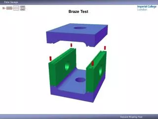
Undulator Vacuum Chamber • Joining Issues • Brazing • Need to evaluate the flange sealing capabilities after undergoing a brazing heating cycle • Welding • Need to determine proper set-up for Cu welding • Shield gas • Heat sinking of piece parts • Pre-Heat? • Need to determine the welding parameters for partial penetration welds on a .5 mm Cu tube.
Undulator Vacuum Chamber • Polishing • Reviewed 26 papers on different forms of Copper Polishing • Three forms of polishing located • Chemical Polishing • Chemical-Mechanical Polishing (CMP) • Electro-Polishing (EP) • CMP and EP very promising • CMP has large body of work from the Semiconductor Industry for planarization of Copper interconnects. Results indicate that the surface finish resulting form this process exceeds what is needed for this application. • EP will need development of the etching solution and the manner that the cathode is placed within the chamber
Undulator Vacuum Chamber Chamber Drawings
Undulator Vacuum Chamber • Status of Prototype • Object: Verify construction methods and fit-up with Undulator • Updating design to current Undulator design • Started Purchasing and Fabrication paperwork • Projected date of completion is November 2004
Undulator Vacuum System / Chamber Design • Vacuum System • System Layout • Short Break Section • Long Break Section • Vacuum Pressure within the System
Vacuum System System Layout
Vacuum System Short Break Section Schematic
Vacuum System • Long Break Section Schematic
Vacuum System Vacuum Pressure within the System (Thermal Desorption only) Red is at Tube Mid-Point Blue is Average Torr hours
Vacuum System • Vacuum Pressure within the System (includes Thermal Desorption plus Photon Stimulated Desorption) Red is at Tube Mid-Point Blue is Average Torr hours
Undulator Vacuum System / Chamber Design • Bellows Module • Design • Status of Bellows Module Design
Bellows Module Design
Bellows Module • Status of Bellows Module Design • Currently, Finessing the Conceptual Design • Need to incorporate with RF-BPM & Quad design team due to space limitation of SB and LB sections • Expect Design Completion: 31 Dec, 2004 • (per P3 Schedule the following items are planned) • Prelim Design Review: 31 Jan, 2005 • Final Design Review: 09 Feb, 2005
Risks / Mitigation • Risks / Mitigation – Vacuum Chamber • Gap clearance between undulator poles / vacuum chamber • Straightness of the copper strongback must be controlled with very small tolerance • Use stitch -welding or E-beam welding to reduce the welding distortion • Inner surface finishing – 100 nm Ra required • After welding – Use Chemical-Mechanical Polishing (CMP) or Electro-Polishing (EP) • Align the overall chamber height (5 supports together) • Use fine screws or compound screws with differential thread
Risks / Mitigation • Risks / Mitigation – Bellows Module • Overall length: expect ~100 mm • Due to space limits in SBS & LBS, must be incorporated with other break components • Lateral offsets: expect ~ ± 3 mm • Use BeCu tube as the sliding RF-fingers within the bellows • Ends of the tube have 0.15 mm slits • Allow the tube to flex radially and provide spring force to maintain contact with the adjacent tube (Tapered stub). • Axial movements : expect ~ ± 5 mm • Ag-plated slits with 0.01 mm (0.4 mil) thick layer • Rd-plated tapered stub with 0.01 mm (0.4 mil) thick layer • Provide a sliding surface with both good lubricity and good electrical conductivity
Undulator Vacuum System / Chamber Design • Conclusions: • Chamber Design progressing • Vacuum System while undergoing small changes is settling down • Bellows is in its initial stage of development • Thanks to: Dr. SH Lee for contributions on the chamber design • Questions
APPENDIX Resulting of Outgassing Calculations