Download
1 / 51
510 likes | 536 Vues
This project aims to create a cost-effective film thickness measurement system for industrial research labs, operating accurately in dirty environments and requiring minimal user input. The system utilizes interferometry principles to quickly and accurately determine film thickness. Design challenges include ensuring accuracy, ease of operation, and compatibility with the existing meniscus experiment. The system design incorporates off-the-shelf components and a MATLAB simulation to analyze experimental data. Test plans involve verifying alignment and testing against known films. Completion plans include LabView integration and user manual development.

E N D
Senior Design II Film Thickness Measurement P06402 Julian Peters Joe Fitzmyer Brad Demers Coordinator: Dr. Wayne Walter Advisor: Dr. Dale Ewbank Sponsor: Dr. Satish Kandlikar
Agenda • Project Overview & Background • Interferometry Background • Analysis • System Operation • System Design • Specifications • Design Challenges • Test Plans • Completion Plans
Project Overview – Sponsor’s Major Needs • Ability to determine existence and thickness of film • Cost-effectiveness • Ability to operate in a “dirty” environment • Accuracy, but not as demanding as semiconductor applications • Must be able to take measurement quickly • Must not require constant input from user
Project Overview - Background • Meniscus Experiment in RIT Thermal Analysis Lab Figure 1: Moving Meniscus Experiment Figure 2: Heater surface and water nozzle detail
Advancing contact line Receding contact line Heated, rotating copper cylinder Direction of Rotation Meniscus Project Overview - Background • Meniscus Experiment in RIT Thermal Analysis Lab • Meniscus Experiment in RIT Thermal Analysis Lab – Unanswered Questions: • Is there a film of adsorbed water left behind the moving meniscus? • How far does it extend? • What is its thickness? Figure 3: Operation of experiment
4) The recombined beam is collected at a sensor. The intensity is measured, and can be compared to the intensity of the original beam. qi 1) Light is emitted from the laser diode. 3)The two reflected beams recombine. The difference in the path length taken by the two beams manifests itself as a phase difference, which can cause attenuation of the beam intensity. Film Surface Substrate Surface 2) Two reflections take place: part of the beam reflects from the film surface, part of it continues through the film and reflects from the substrate surface. Interferometry in a Nutshell Figure 5: Interferometry Basics
for s-polarization for p-polarization for s-polarization for p-polarization Interferometry Analysis
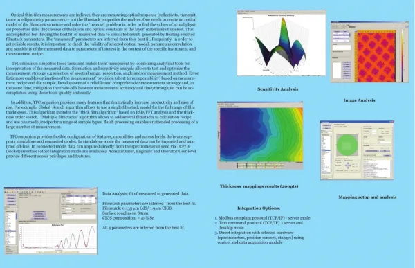
Analysis of Design • MATLAB code written to simulate reflectance response • Data from numerical experiments • Determine appropriate wavelengths • Analyze experimental data • Most easily identified noise independent parameter of data is the frequency of oscillations
Sample MATLAB Results Figure 10: Oscillatory Reflectance Response
Sample MATLAB Results Figure 11: Non-Oscillatory Reflectance Response at Zero Film Thickness
MATLAB Code Verification Figure 12: Comparison of WVASE32 and MATLAB Results
Control Hardware Goniometer Actuators Information Control Laser Diode Power Operator PC Light reflected from surface LabView Data Collection Hardware Photosensor Figure 6: Information and control flow through system Basic System Diagram
Off-the-Shelf Components • Laser diode: CPS196 • Goniometers: GNL10-Z6 • Motor Controller: ODC001 • TI OPA129U • NI USB DAQ 6008 • Photodiode: SM05PD1A
System DesignPhysical System Assembly Goniometer Photodiode Servo Controller Servo Controller Substrate and Film Breadboard Base Laser Diode
System DesignPhysical System Assembly Goniometer Servo Controller Servo Controller Substrate and Film Breadboard Base Base
Specifications & Targets • Positioning Accuracy – ± 0.25° • Positioning Precision – ± 0.25° • Film Thickness Accuracy – ± 5 μm • Film Thickness Precision – ± 5 μm • Measurement Time – 30 minutes
Design Challenges • Light Source • Beam divergence • Suitability of wavelength to film thickness • Consistency of intensity • Polarization intensity • Focal length • Photodiode • Must accommodate beam divergence • Accuracy
Design Challenges • Positioning Equipment • Accuracy • Repeatability • Synchronicity • Alignment • Equipment Mounts • Accuracy • Compensating
Design Challenges • PC Interface Hardware / Software • Position control and reporting • Single user input • Collect data from photodiode • Data Interpretation Programming • Fit data to simulation • Measure of confidence
Design Challenges • Specific Application to Mensicus Experiment • Optical properties of surface • Beam alignment • Flatness of surface
Alignment and Calibration • Goniometer zeroes • Calibration curve • Verify alignment
Alignment and Calibration “Zero” is found by reflecting laser back onto itself. 51” Linear-to-angular step size is found by making marks on target at regular linear steps. q
Test and Completion Plan • Verify assembly alignment • Labview code • Test against known films • Implement Matlab code • User manual