Download
1 / 21
210 likes | 408 Vues
An Integrated Robotic Laser Range Sensing System for Automatic Mapping of Wide Workspaces. P. Curtis P. Payeur University of Ottawa. Introduction. Range data acquisition of cluttered workspaces is tedious using currently available point/line laser range scanners

E N D
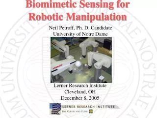
An Integrated Robotic Laser Range Sensing System for Automatic Mapping of Wide Workspaces P. Curtis P. Payeur University of Ottawa
Introduction • Range data acquisition of cluttered workspaces is tedious using currently available point/line laser range scanners • To create a practical 3-D model, range data from multiple view points are required • Through the use of a laser range finder mounted on a robotic arm the data acquisition process is simplified
Introduction • Included software tools of both the laser range finder, and the robotic arm do not allow for a seamless one step automatic process • Human interaction increases the probability of errors, and time required to acquire data, and decreases repeatability • The human interaction solution is therefore not practical in an industrial environment • Solution is to create a semi-autonomous system with a minimal amount of human interaction
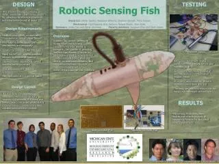
Equipment • The equipment which is currently being applied to the problem is: • CRS-Robotics F3 serial robotic manipulator mounted upon a CRS 2m track • Servo-Robot Jupiter laser line scanner • Windows 2000 workstation
Robotic Arm • The CRS F3 mounted on the 2m track provides 7 degrees of freedom • The robotic arm is controlled by a CRS C500C controller
Robotic Arm • Interaction with the robotic arm occurs via RS-232 asynchronous link to the C500C controller • The manufacturer supplied RAPL-3 language allows for the development of applications for the robotic system
Laser Range Scanner • The Jupiter laser line scanner exploits the well-known synchronized triangulation technology developed at NRC. • This Laser Range scanner can acquire 256 or 512 points per scan along a single line.
Laser Range Scanner • The Servo-Robot Cami-Box controls the range scanner • Interaction with the laser line scanner occurs though a RS-232 asynchronous link with the Cami-Box • The Jupiter laser line scanner was chosen due to its large scan range (1m) and its physical attributes (light and compact)
Laser Range Scanner • The manufacturer supplied Winuser software contains functionality to acquire range images, but the data is saved to a proprietary format, and requires too much human interaction
System Hardware Integration • An Intel based machine running Windows 2000 interfaces with the manipulator controller and with the Jupiter scanner controller via 2 RS-232 asynchronous links. • The Jupiter scanner is mounted on the CRS F3 robotic manipulator
System Software Integration • Using the documentation for the CRS C500C, the Servo-Robot Cami-Box, and the Microsoft WIN32 API, software control modules were developed. • Of particular note commands to move robot joints, to turn on/off the laser line scanner, and to acquire data were implemented • An inverse kinematics solution was developed based upon that developed by W.M. Keck Virtual Factory Lab.
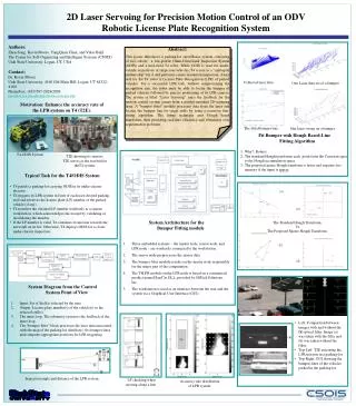
System Software Integration • These modules were integrated together and a Windows GUI was developed • The GUI allows the entry of the following parameters: • starting position and orientation (which is encoded into an homogeneous transformation matrix - S) • Scanning vector which defines the direction and magnitude of each step in a scan (also a homogeneous transformation matrix – D) • Number of steps in the scan (N)
System Software Integration • Using these limited parameters it is possible to scan a surface with a desired resolution and size • Data acquired is saved to a single file
System Software Integration • The process to acquire a complete scan is as follows: • The current scan position (P) is determined by the starting transformation matrix (S), and the step transformation matrix (D) multiplied by itself n times, where n represents the current step number and is between 0 and N, in other words the current position is: P=SDn 2. Once the scan position is computed, the robot inverse kinematics solution is used to generate the 7 joint values
System Software Integration 3. The robot control module then moves each of the joints to their respective angular position 4. Once the robot is finished moving, the laser is turned on, the line of data is acquired, and the laser is turned off. The range data is kept in a temporary memory with the corresponding pose of the sensor • The first 4 steps are repeated until n=N • Once the scanning trajectory is complete, the operator clicks on a button on the graphical interface to automatically save the acquired data to a specified file
Results – Using Human Interation • Using the Manufacturer supplied software with human interaction for each step in the scanning process, the time to acquire 64 lines of data from a series of 3 different viewing areas in a large fixed environment was on the order of a day (excluding the merging of the data) • Results had a low repeatability and precision due to the manual driving of the manipulator to the desired position
Results – Using Semi-Autonomous System • Using the approach described, acquiring 64 lines of data from 3 different view points in a large fixed environment takes about 2 hours • Maximal precision is ensured throughout the whole process, since registration precision is maintained for every position. • Repeatability is increased due to the use of the computer controlled solution, and its inherently high precision
Results – Sample Data • The sample scan (lower image) is of the mock-up chair (see upper image) and contains 64 lines at a 4mm line spacing. • The data visualization is through a matlab script.
Conclusions • The improvement of the semi-autonomous system over the previous system of human interaction at each step is primarily illustrated though the drastic improvement of acquisition time (about 5x improvement) • Precision and repeatability are ensured through the minimization of human interaction in the data acquisition process
Future Work • Currently the manipulation of the robotic joints occurs serially (i.e. one joint is moved at a time). By changing the design to allow all joints to move simultaneously, a further increase in scanning speed can be realised • Currently the laser line scanner is toggle on and off for each line of data acquired. By leaving the laser on for the whole scan, a further increase in scanning speed can be realised • Different scanning patterns are being investigated, as well as visualisation techniques
Questions/Acknowledgments • E-mail • P. Curtis: pcurtis@site.uottawa.ca • P. Payeur: ppayeur@site.uottawa.ca • The authors wish to acknowledge the support of the Canadian Foundation for Innovation and the Ontario Innovation Trust as well as the Faculty of Engineering of the University of Ottawa for their support that made this research work possible.