Download
1 / 70
710 likes | 878 Vues
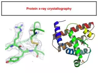
From Papertape Input to ‘Forensic Crystallography’ A History of the Program PLATON. Ton Spek, Bijvoet Center Utrecht University The Netherlands K.N.Trueblood Award Lecture Chicago, July 29, 2010. Some History.

E N D
From Papertape Input to ‘Forensic Crystallography’A History of the Program PLATON Ton Spek, Bijvoet Center Utrecht University The Netherlands K.N.Trueblood Award Lecture Chicago, July 29, 2010.
Some History • Back in 1966 I started crystallography as a student in the Laboratory for Crystal and Structural Chemistry at Utrecht University that was at that time headed by Prof. A.F. Peerdeman. • Peerdeman (co-author of the famous Bijvoet, Peerdeman & van Bommel paper on absolute configuration) was the successor of Prof. J.M.Bijvoet. • Dorothy Hodgkin came over during that time to tell about the Vitamin B12 structure and her oversees collaboration with Ken Trueblood
After WWII, Bijvoet had Managed to start a new lab in a stately house (used by the Gestapo during WWII) close to the centre of the city of Utrecht. Part of the house was his private domain. After his retirement, he still kept a pied-a-terre for when he was in Utrecht. As a student, I shared the family bedroom … in its double function as student room.
Computing-I • The Crystal Palace was the home of the first two generations of computing platforms within the university of Utrecht (Zebra and X1 respectively). • In 1966 computing had moved to a University computing centre elsewhere in the city. • Computing was done from then on with an Algol language specific X8 computer (From a Dutch company Electrologica, later part of Philips) • Processing was essentially one job at a time.
16kW ~1966, Electrologica X8 ALGOL60 ‘Mainframe’ (<1MHz)
Computing-II • Jobs were run by an operator during daytime shifts • Most of our crystallographic work was done during the once-a-week 13 hour nightshift when we as crystallographers had the computer for ourselves. Half of the staff stayed overnight. • We were during that nightshift the scientist, the software developer and the system operator in one. • I/O was paper tape based. One job at a time. Very little memory. No stored binaries, thus recompilation everytime.
Computing-III • Programs and data were on paper tape • The preparation of programs and program input were done on the so called Flexowriter. This very noisy electical typewriter was also often used as output medium. • Editing was done with a pair of sissors to cut out unwanted material from the source code and adhesive tape to glue a substitute in the paper tape.
Flexowriter for the creation and editing of programs and input data
The Science • My supervisor, Dr. J.A. Kanters, gave me an interesting assignment to work on. • He handed me a batch of white crystals with unknown composition (code named M200). • The assignment was to find out what was the structure, using single crystal X-ray techniques only.
Data Collection for M200 • Preliminary investigations done with film data pointed at space group P-1. • A Patterson synthesis based on integrated Weissenberg projection data subsequently suggested a light atom structure. • Eventually a three-dimensional data set was collected with an Enraf-Nonius AD3 diffractometer (two weeks of datacollection !).
Structure Determination of M200 • It took half a year to finally find the structure. • The laboratory had a tradition in Direct Methods (Beurskens, de Vries, Kroon, Krabbendam) • However, all available software failed to solve my structure (these were pre-MULTAN days ..) • In the end I had to write my own Direct Methods program (AUDICE) that solved the triclinic structure including many other unsolved structures that were hanging around in the lab.
The Structure 3-Methoxy-glutaconic acid
The Program AUDICE • AUDICE was one of the Symbolic Addition programs that were developed in that period. • Its specialty was that at the start of the evaluation of the strong triple product indications for a positive sign, 27 symbols were introduced for strong starting reflections rather than in the order of three by some other approaches. Eventually, 8 solutions were produced by eliminating 24 symbols based on multiple ‘indications’. • In addition the ‘correlation method’ was used to improve the reliability of triple phase relations.
The Correlation Method P+ for triple H,K,H+K depends on |E(H)E(K)E(H+K)| ‘Correlation Method’ Improved P+ on the basis of P+ of three adjacent triples |E(H)E(L)E(H+L)| |E(K)E(L-K)E(L)| |E(H+K)E(L-K)E(H+L)| I.e. Strengthening of P+(|E(H)E(K)E(H+K)| when in addition E(H+L),E(L-K),E(L) strong (Note: Theoretically formalized in terms of neighbourhoods, Hauptman) L H K H+K
Epilogue • The structure of M200 has been published • Unfortunately, attempts to publish AUDICE in Acta Cryst. stranded on the referee requirement to compare its performance on non ALGOL (real ..) platforms. • Anyway AUDICE was superseded by the program MULTAN (Fortran) on the new CDC University Mainframe. • The structure solves and refines in a matter of seconds on current hardware with SYSTEM S =>
Automatic Structure Solution of M200 in the No-Questions-Asked Mode
Direct Methods Meetings • Multiple meetings and schools were organized in the 70’s with Direct Methods (software and theory) as its major subject. • Examples are the NATO schools in Parma and York, the schools in Erice (1974 & 1978) and the meetings at the Medical Foundation (Buffalo) where I met Ken Trueblood. • Important one’s werealso the CECAM workshops on Direct Methods (5 weeks!, bringing together people working in the field to work on current issues) in the early 70’s in Orsay (near Paris) around a big IBM-360 with lectures by Hauptman. (Participants: Germain, Main, Destro, Viterbo). The program MULTAN was finalized there. • Photo of the participants of the Parma 1973 meeting and the 1978 Erice School next :
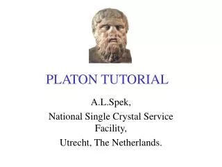
The National Facility • In 1971, a national single crystal service facility was started, with me to make it all happen.. • I kept that position for 38 until my emeritus status in 2009. • The project is now continued by my former co-worker Martin Lutz • My last postdoc was Maxime Siegler, now staff crystallographer at the John Hopkins University. • The program PLATON is a side product of the national facility (note: never explicitly funded !)
PLATON • Work on PLATON started in 1980. • The idea was to produce with a single ‘CALC ALL’ instruction an exhaustive listing of derived geometry to give to our clients. • Over time numerous additional tools have been added on the basis or the needs in our service setting. • PLATON is, in combination with SHELX, one of the major tools for our service.
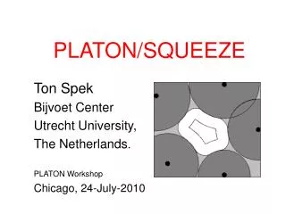
PLATON Tools • The available tools are shown as clickable options on the opening window of the program. • Examples are ADDSYM for the detection of missed symmetry, TwinRotMat for automatic twinning detection and SYSTEM S for guided/automated structure determination) • Here we will look in some detail at a few of the tools: • SQUEEZE for the handling of disordered solvents • Structure Validation (used as part of the IUCr CheckCIF) • FLIPPER, a new approach to structure determination
The Disordered Solvent Problem • Molecules of interest often co-crystallize (only) with the inclusion of a suitable solvent molecule. • Solvent molecules often fill voids in a structure with little interaction and located on symmetry sites and with population less than 1.0 • Often the nature of the (mixture) of included solvent(s) is unclear. • Inclusion of the scattering contribution of the solvent can be done either with a disorder model or with SQUEEZE.
THE MOLECULE THAT INVOKED THE BYPASS/SQUEEZE TOOL Salazopyrin from DMF – R = 0.096
Structure Modeling and Refinement Problem for the Salazopyrin structure Difference Fourier map shows disordered channels rather than maxima How to handle this in the Refinement ? SQUEEZE !
Looking down the Infinite Channels in the Salazopyrin Structure How to model this disorder in the L.S-Refinement ?
The SQUEEZE Tool • The SQUEEZE tool offers an alternative to the refinement of a disorder model for a structure containing disordered solvent. • The contribution of the disordered solvent to the calculated structure factors is taken into account by back-Fourier transformation of the electron density found in the solvent region of the difference map. • This requires an iterative series of difference map improvements. • Firstly, the solvent accessible region has to be indentified to be used as a mask over the difference density map.
Solvent Accessible Voids • A typical crystal structure has only in the order of 65% of the available space filled. • The remainder volume is in voids (cusps) in-between atoms (too small to accommodate an H-atom) • Solvent accessible voids can be defined as regions in the structure that can accommodate at least a sphere with radius 1.2 Angstrom without intersecting with any of the van der Waals spheres assigned to each atom in the structure. • Next Slide: Void Algorithm: Cartoon Style
DEFINE SOLVENT ACCESSIBLE VOID STEP #1 – EXCLUDE VOLUME INSIDE THE VAN DER WAALS SPHERE
DEFINE SOLVENT ACCESSIBLE VOID White Area: Ohashi Volume. Location of possible Atom centers STEP # 2 – EXCLUDE AN ACCESS RADIAL VOLUME TO FIND THE LOCATION OF ATOMS WITH THEIR CENTRE AT LEAST 1.2 ANGSTROM AWAY
The DEFINE SOLVENT ACCESSIBLE VOID STEP # 3 – EXTEND INNER VOLUME WITH POINTS WITHIN 1.2 ANGSTROM FROM ITS OUTER BOUNDS
Listing of all voids in the unit cell The numbers in [ ] refer to the Ohashi Volume EXAMPLE OF A VOID ANALYSIS
VOID APPLICATIONS • Detection of Solvent Accessible Voids in a Structure • Calculation of Kitaigorodskii Packing Index • Determination of the available space in solid state reactions (Ohashi) • Determination of pore volumes, pore shapes and migration paths in microporous crystals • As part of the SQUEEZE routine to handle the contribution of disordered solvents in a crystal structure.
SQUEEZE • Takes the contribution of disordered solvents to the calculated structure factors into account by back-Fourier transformation of density found in the ‘solvent accessible volume’ outside the ordered part of the structure (iterated). • Refine with SHELXL using the solvent free .hkl • Or CRYSTALS using the SQUEEZE solvent contribution and the the full Fobs • Note:SHELXL lacks option for fixed contribution to Structure Factor Calculation.
SQUEEZE Algorithm • Calculate difference Fourier map (FFT) • Use the VOID-map as a mask on the FFT-map to set all density outside the VOID’s to zero. • FFT-1 this masked Difference map -> contribution of the disordered solvent to the structure factors • Calculate an improved difference map with F(obs) phases based on F(calc) including the recovered solvent contribution and F(calc) without the solvent contribution. • Recycle to 2 until convergence.
SQUEEZE In the Complex Plane Fc(solvent) Fc(total) Fc(model) Fobs Solvent Free Fobs Black: Split Fc into a discrete and solvent contribution Red: For SHELX refinement, temporarily substract recovered solvent contribution from Fobs.
Real World Example • THF molecule disordered over a center of inversion • Comparison of the result of a disorder model refinement with a SQUEEZE refinement
Disorder Model Refinement Final R = 0.033
Comparison of the Results of the two Modeling Procedures Disorder Model R = 0.033 SQUEEZE Model R = 0.030
Concluding Remarks • The CSD includes in the order of 1000 entries where SQUEEZE was used. • Care should be taken for issues such as charge balance
Charge Flipping • Charge Flipping as an alternative for structure solution by Direct Methods was introduced by G. Oszlanyi & A. Suto (2004). Acta Cryst. A60, 134. • Similar to SQUEEZE it involves iterated forward and backward Fourier transforms. • PLATON implements an experimental version of Charge Flipping named FLIPPER. • Following is an example of the P21, Z=2 structure of vitamin C solved by FLIPPER starting with all reflections assigned a phase of zero degrees.
FLIPPER • Charge Flipping is done with data in space group P1. • The space group is determined from the solution • The methods can be used for automatic structure determination of non disordered structures • Following is the real time display of the progress in the development of the structure after each Fourier cycle, followed a full refinement.