Download
1 / 34
340 likes | 362 Vues
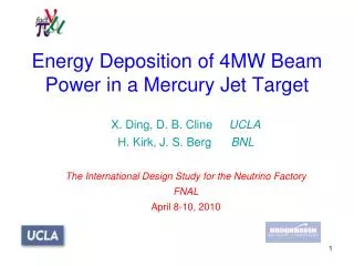
Explore the inter-dependency of key parameters in proton driver for material R&D at NFMCC meeting, UCLA, CA. Investigate effects of irradiation on material properties, voids/dislocations generation, and changes in physical/mechanical properties. Analyze various materials like Inconel-718, carbon composites, super-Invar, etc., under irradiation. Evaluate the behavior of carbon composites under thermal cycling and self-healing reactions. Re-assess high-Z range materials and super-alloys for proton irradiation studies.

E N D
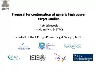
High Power Target Material R&D N. Simos, BNL NFMCC Meeting, UCLA, CA
4 MW proton driver? Operational Envelope & Inter-dependency of KEY parameters Desired bunch length as low as 2 ns !!! NFMCC Meeting, UCLA, CA
Solid Targets – How far can they go? NFMCC Meeting, UCLA, CA
R&D on irradiation damage What does it mean for materials (microscopic & macroscopic terms) ?generation of voids/dislocations changes in physical and mechanical propertiestrapping of gases, swelling density reduction Effects of neutron irradiation from reactor experienceQuestion: does radiation type matter? NFMCC Meeting, UCLA, CA
Irradiation takes place at BLIP using 200 MeV or 117 MeV protons at the end of Linac Experimental Process Utilizing BNL Accelerator Complex BEAM on Targets Bldg 801 Post irradiation analysis at BNL Hot Labs Remotely operated mechanical testing system Thermal Expansion/Heat Capacity Measuring System NFMCC Meeting, UCLA, CA
IRRADIATION STUDIES PHASE I: Super Invar and Inconel-718 PHASE II: • 3D Carbon-Carbon Composite • Toyota “Gum Metal” • Graphite (IG-43) • AlBeMet • Beryllium • Ti Alloy (6Al-4V) • Vascomax • Nickel-Plated Alum. BEAM • PHASE II-a: • 2D Carbon-Carbon PHASE III: • 3D & 2D Carbon-Carbon • 90% cold-worked “Gum Metal” • Graphite (IG-43 & IG-430) • AlBeMet • Ti Alloy (6Al-4V) • Copper & Glidcop • W and Ta • Vascomax • Nickel-Plated Aluminum • Super-Invar following annealing • Graphite/titanium bonded target NFMCC Meeting, UCLA, CA
PHASE III - Preparations NFMCC Meeting, UCLA, CA
Specially bonded graphite/titanium target exposed to proton irradiation NFMCC Meeting, UCLA, CA
Graphite vs. Carbon-Carbon 3D CC NFMCC Meeting, UCLA, CA
3D CC Annealing Behavior !! Radiation changes material dramatically Thermal cycling restores it 45-degree plane (“weak” orientation) 90-degree fiber orientation Good news were associated with modest beam exposure (~ 25,000 uA-hrs). More needed to be done to validate that carbon composites can replace graphite. NFMCC Meeting, UCLA, CA
Embarked into a 2-phase new study Phase 1 Assess the 2D carbon-carbon under heavy irradiation Phase 2 Expose 2D & 3D carbon-carbon composites under identical experimental conditions NFMCC Meeting, UCLA, CA
Phase-1: 2D Carbon Composite PEAK integrated flux achieved ~ 7 x 10^21 protons/cm^2 Integrated beam current ~ 108,000 uA-hrs Post-irradiation analysis of the exposed 2-D carbon composite revealed both good and bad news: GOOD NEWS: the composite exhibits self-healing behavior (as in the case of the 3-D counterpart) BAD NEWS: Serious structural degradation is observed as a result of high fluences Damage more pronounced along the “weak” orientation NFMCC Meeting, UCLA, CA
Good News: 2D carbon composite exhibits self-healing through thermal annealing Compare with 3D counterpart “strong” orientation NFMCC Meeting, UCLA, CA
How well is our nanometer-level analysis controlled/stabilized? 2.70 mCi 4.62 mCi 7.62 mCi 8.08 mCi COMPARE ! NFMCC Meeting, UCLA, CA
Bad News: Structural degradation “strong” orientation “weak” orientation NFMCC Meeting, UCLA, CA
“Unexpected” 2-D CC damage left us scratching our heads Is it just the 2D carbon composite that is susceptible to high fluences OR This holds true will ALL carbon composites (2D & 3D) ? The mixed-bag of news prompted us to go through another exposure where 2D and 3D carbon composites are irradiated under identical conditions Irradiation of the two carbon composites along with two graphite grades (IG-43 and IG-430) was performed in Spring 2006. Integrated current reached ~ 50,000 uA-hrs (but likely under tighter beam spot!!) NFMCC Meeting, UCLA, CA
PRELIMINARY assessment of exposures 2005 Irradiation 2006 Irradiation Nickel foils of the 2006 irradiation are currently being analyzed (radiography) to establish shape of proton beam NFMCC Meeting, UCLA, CA
Damage in 3-D carbon composite. Note the complete disintegration of irradiated specimens situated within the 1-sigma of the beam NFMCC Meeting, UCLA, CA
Damage even worse in 2-D carbon composite. Severe disintegration especially of “weak-orientation” falling within 1-sigma of the beam NFMCC Meeting, UCLA, CA
BACK TO THE DRAWING BOARD NFMCC Meeting, UCLA, CA
Take another look at super-InvarLook into other super-alloys (gum metal, titanium alloys, etc.)Explore new graphite gradesFurther evaluate AlBeMetRe-assess high-Z range (Ta, W) NFMCC Meeting, UCLA, CA
Re-evaluation of super Invar Modest level of irradiation takes away the low thermal expansion exhibited by the un-irradiated super Invar Thermal cycling with temp. threshold identified experimentally as Tthreshold > 600 C restores material !! NFMCC Meeting, UCLA, CA
Re-evaluation of super Invar Remote RE-ASSEMBLY in Hot Cell Half of layer undergone annealing (>600 C) Back in the “OVEN” !!! NFMCC Meeting, UCLA, CA
Questions to be answered regarding annealing • How is irradiation damage influenced by high temperatures during irradiation and if yes where is the threshold? • A difficult but not impossible task – achieve same exposure at different irradiation temperatures • Identifying the temperature threshold will allow for life extension of the material in the irradiation environment • Do materials exhibit similar damage following annealing and re-irradiation ? • Studies from neutron exposure indicate that the number of voids, while decrease in size, increase in number during re-irradiation • To address that, irradiated and then annealed super-Invar has been exposed to irradiation NFMCC Meeting, UCLA, CA
Radiation effect on ductility & strength – How important is ductility? NFMCC Meeting, UCLA, CA
Enhancement of properties are attributed to the “dislocation-free” plastic deformation mechanism The high expectations of gum metal Super ductility completely disappears with irradiation 1st Cycle 2nd Cycle NFMCC Meeting, UCLA, CA
Serious degradation of magnetic horn material (nickel-plated aluminum) used in the NuMI experiment at FNAL! Retested during Phase III with double the exposure and waiting examination After irradiation Before irradiation NFMCC Meeting, UCLA, CA
SUMMARY The value of performing R&D prior to moving too far ahead based on “expectations” has been clearly demonstrated Further experimental scrutiny of 2D or 3D carbon composites for irradiation damage effects is not recommended. These composites clearly CANNOT tolerate the high fluences required by high-power beam targets. These results should prompt a change of course in the search for materials for the multi-MW beam targets. FOCUS needs to be shifted toward: • Low-Z: new graphite grades such as isotropic graphite IG-430 and AlBeMet • Mid-Z: Titanium alloys, Vascomax, super-Invar • High-Z: New alloys of Ta and W NFMCC Meeting, UCLA, CA
Some interesting irradiation damage findings !!! NFMCC Meeting, UCLA, CA
Four 1-mm rods and Aluminum container Copper foil container Aluminum holder three 2-mm rods D~(17+1) mm D~5mm D~72 mm Container 1 Container 2 Beam Container 3 50mm Quartz Aluminum Copper Ceramics/Resistors/Capacitors integrated with quartz rods and CZT crystals Resistors Capacitors Ceramic TYPE A Ceramic TYPE B NFMCC Meeting, UCLA, CA CZT Crystals
Neutron Exposure NFMCC Meeting, UCLA, CA
Crystal (SO2) AFTER irradiation Crystal (SO2) before irradiation Crystal (SO2) AFTER irradiation NFMCC Meeting, UCLA, CA