Download
1 / 6
70 likes | 138 Vues
“Traditional” treatment of quantum noise. Shot Noise Uncertainty in number of photons detected a (Tunable) interferometer response T ifo depends on light storage time of GW signal in the interferometer Radiation Pressure Noise

E N D
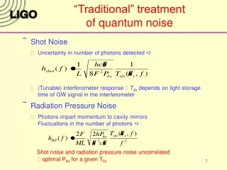
“Traditional” treatment of quantum noise • Shot Noise • Uncertainty in number of photons detected a • (Tunable) interferometer response Tifo depends on light storage time of GW signal in the interferometer • Radiation Pressure Noise • Photons impart momentum to cavity mirrorsFluctuations in the number of photons a Shot noise and radiation pressure noise uncorrelated optimal Pbs for a given Tifo
The quantum calculationDC strain sensitivity • Buonanno and Chen (PRD 2001) • In signal tuned interferometer shot noise and radiation pressure (back action) noise are correlated • Optical field (which was carrying mirror displacement information) returns to the arm cavity radiation pressure force depends on test mass motion • Quantized quadrature fields (quantum treatment not necessary when input at SRM is vacuum, can use classical amplitude/phase fluctuations) • Use commutation relations for creation and annhilation operators, correlated two-photon modes
Homodyne (DC) readout • z0 = homodyne phase • k = coupling constant (ISQL, I0, W, g) • F, f = GW sideband, carrier phase gain in SR cavity • = GW sideband phase gain in arm cavity r, t = SRM reflection, transmission coefficient Cij, M, D1,2 = f(r, f, F, k, b)
Heterodyne (RF) readout fD = RF demodulation phase D+,- = (complex) amplitude of upper, lower RF sideband
h(f) (1/rtHz) frequency (Hz) Preliminary result (not yet correct?)
h(f) (1/rtHz) frequency (Hz) No crossings no frequency dependent optimal demod phase