AC Circuits Using Complex Exponentials
260 likes | 424 Vues
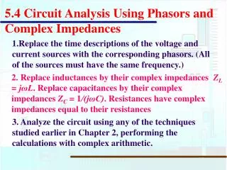
Explore the application of complex exponentials in analyzing AC circuits, including phasor representation, circuit analysis, and resonance phenomena. Learn about phasors, impedance, and frequency domain through Euler's Formula and DeMoivre's Theorem. Dive into phasor transforms and the advantages they offer for solving electrical circuits.

AC Circuits Using Complex Exponentials
E N D
Presentation Transcript
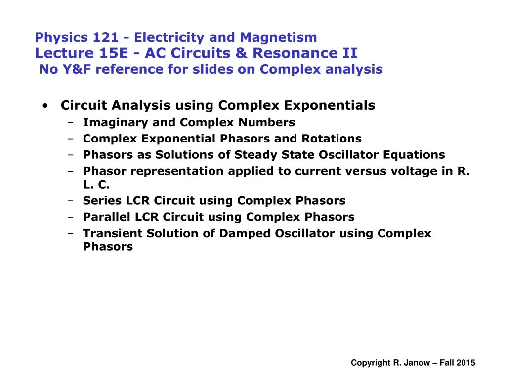
Physics 121 - Electricity and MagnetismLecture 15E - AC Circuits & Resonance II No Y&F reference for slides on Complex analysis • Circuit Analysis using Complex Exponentials • Imaginary and Complex Numbers • Complex Exponential Phasors and Rotations • Phasors as Solutions of Steady State Oscillator Equations • Phasor representation applied to current versus voltage in R. L. C. • Series LCR Circuit using Complex Phasors • Parallel LCR Circuit using Complex Phasors • Transient Solution of Damped Oscillator using Complex Phasors
vR Circuit Element Symbol Resistance or Reactance Phase of Current Phase Angle Amplitude Relation E R Resistor R R In phase with VR 0º (0 rad) VR = ImR L vL C Capacitor C XC=1/wdC Leads VC by 90º -90º (-p/2) VC = ImXC vC Inductor L XL=wdL Lags VL by 90º +90º (p/2) VL = ImXL Em Im F VL-VC Z VR XL-XC wDt R sketch shows XL > XC Summary: AC Series LCR Circuit
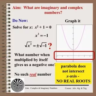
Roots of a quadratic equationaz2 + bz +c = 0 are complex if b2<4ac: • Complex conjugate: Complex Exponentials in Circuit Analysis is “pure imaginary” • Complex number in rectangular form: REVERSE SIGN OF IMAGINARY PART • Re{z} and Im{z} are both real numbers • Addition: • EE’s use j instead of i (i is for current)
Representation using the Complex Plane Imaginary axis (y) |z| y q x Real axis (x) • Polar form: • Magnitude2: “Argand diagram” • Argument: • Picture also used to display complex-valued functions
Complex Exponentials: Euler’s Formula • The real & imaginary parts are series for sine and cosine: • Hence: Above is a complex number of magnitude 1, argument q: • Special • Properties: • Taylor’s Series definition of exponential function: • Evaluate with u = iq: use i2n+1 = i(-1)2n
Rules for Complex Quantities Euler’s Formula with magnitude r: Polar form of arbitrary complex z Complex conjugate of z Product: • Magnitude of a product = product of individual magnitudes • Argument of a product = sum of individual arguments • Two complex entities are equal if and only if their amplitudes • (magnitudes) are equal and their arguments (phases) are equal Sum: Periodicity 2p: DeMoivre’s Theorem: for integer n & k = 0,1….n-1
Time Evolution: Let f = w(t-t0) Represent sinusoidally varying real quantity a(t) as a vector in the complex plane, rotating (counterclockwise) at angular frequency w. Im • A(t)is called a “time domain phasor” • Re {A(t)} is the measurable instantaneous value of A(t) • Time dependent exponentials like eiwt are sometimes called evolution operators • Cancelling common factors of eiwt leaves a “frequency domain phasor” A (often • simply called a “phasor”): +f -f q Re evolves z from t0 to tf for tf > t0 Phasors, Rotation Operators, Evolution Operators: e+if rotates complex number z by angle +f in complex plane
Phasor Definitions, continued time domain phasor, complex peak value of a(t), real instantaneous value, time domain, real frequency domain phasor A, complex, rotated by f from real axis Phasor Transform Operator P: Forward - time to frequency domain: Inverse - frequency to time domain: Advantage of phasor transform: For sinusoidal signals, differential equations (in the time domain) become algebraic equations (in the frequency domain) as common factors of eiwt cancel). Process:Replace real variables in time dependent analysis problem with variables written using complex exponentials. Cancel common factors of eiwt and solve remaining algebraic problem. Then return to real solution in time domain. A phasor represents a sinusoidal, steady state signal whose amplitude Amax, phase f, and frequency w are time invariant.
Time domain phasors are alternative solutions to sines and cosines in differential equations representing oscillations. Recall: chain rule: a can be complex First and Second Derivatives: set a = wt+f, amplitude Amax Example: Simple Harmonic Oscillator Trig Solutions: Complex Solutions:
Complex Exponential Representation applied to Passive Circuit Elements: Revisit AC Voltage vs. Current in L, C, and R i(t) Resistor: vR( t ) magnitudes: exponents: i(t) Inductor: L vL(t) magnitudes: i(t) exponents: Capacitor: vC ( t ) C magnitudes: exponents: Apply complex voltage & current (time domain phasors): Note: now using j = sqrt(-1)
Summary: Complex Exponential Representation of AC Voltage vs. Current in L, C, and R Applied voltage: & current: time domain VL leads ILm by p/2 VR& IRm in phase VC lags ICm by p/2 Rotations of voltage drop phasors relative to current phasor: e-jp/2 = -j e0 =1 e+jp/2 = +j Voltage drop phasors relative to currents: time domain Frequency domain (factor out time dependence) Define: Complex impedance z = E(t)/i(t) and |z| = Vmax/Imax Impedances of simple circuit elements (complex) are: Magnitudes of Impedances |z| = [zz*]1/2 (real) Phase angle factor ejFrotates E CCW from the current phasor Passive circuit elements: Resistor: Inductor: Capacitor:
Complex Impedance z Im Em Z Definition:Phase angle F measures rotation of the applied voltage referenced to the current in the branch. It is also the angle between z and the real axis. The rotation operator is ejF. Im(z) Im F • Sketch shows positive Im{z}. • is positive, implying that Em leads Im. Re Re(z) 1/z occurs when analyzing parallel branches: Applied voltage: & current: time domain Definition: complex impedance z (or simply impedance) is the ratio of the (complex) voltage phasor to the (complex) current phasor (in time or frequency domain).
The kth sub-circuit (arbitrary complexity) consists of R, L, and/or C basic elements: zk zk z2 z1 zk z1 z2 Impedances of Series or Parallel Collections of Circuit Elements Impedances of individual passive circuit elements: Assertion: Follow series or parallel resistor addition rules to compute equivalent impedances (complex) Series branch formula: Parallel sub-circuit formula:
Revisit series LCR circuit using complex phasors AC voltage: vR Current: E R L vL C vC Divide equation (1) by i(t) ( = Imejwt ) Magnitude of Z: VL Em Im F wDt VR Sketch shows F positive for VL>VC XL>XC A t = 0 sketch would show phasors in frequency domain VC time domain phasors Currents are the same everywhere in an essential branch, same phase, same magnitude. Kirchhoff Loop rule for series LRC circuit: Substitute the time domain voltage phasors for vR, vL, vC.
Revisit the series LCR circuit, Continuation Impedance z (Equation 1) can also be found by summing the impedances of the 3 basic circuit elements in series LCR circuit (invoke Series Formula*) Im Z XL-XC F z is not a phasor, as it is time independent. Previous “phasor diagrams” showed z rotating with Em. Re R Phase angle F for the circuit: Power factor: Phase angle in terms of admittance 1/z: Sketch shows F >0 for XL > XC VL > VC. F is positive when Im{z} is positive * The equivalent (complex) impedance for circuit elements in series (arbitrarily many) is the sum of the individual (complex) impedances. Resonance: As before, z is real for XL= XC (w2= 1/LC). |z| is minimized. Current amplitude Im is maximized at resonance
Parallel LCR circuit using complex phasors a iL iC iR E vL vR R C L Kirchhoff Loop Rule (time domain): b vC • 2 essential nodes “a” & “b” • 4 essential branches, • Not all independent Instantaneous voltages across parallel branches have the same magnitude and phase: Use voltage as reference instead of current i Common voltage peak, all branches: Common voltage phase, all branches: Kichhoff Current Rule (node a or b): Current Amplitudes in each parallel branch (reference now to voltage drop): All steady state voltages and currents oscillate at driving frequency wD AC voltage: Instantaneous Current:
Parallel LCR circuit, Continuation #1 Im Em, VR, VL, VC IRm • in phase with E(t) F Im wDt • lags E(t) by p/2 ICm • leads E(t) by p/2 ILm Re ICm- ILm Current amplitude addition rule is Pythagorean Substitute currents into junction rule equation (1): Cancel ejwt factor and multiply by e-jF (current phasor – frequency domain) Instantaneous currents in each branch lead, lag, or are in phase with the (reference) voltages: Sketch shows F < 0 (applied voltage lags current) for ICm > ILm XL>XC
Parallel LCR circuit, continuation #2 Note that: Substitute, then divide (Eq. 2.1) above by Em Find |1/z|: multiply 1/z by complex conjugate (1/z)* and take square root: Represent z in terms of 1/z: Recall, impedance “admittance” Admittance 1/z in Equation 3 is also the sum of the reciprocal impedances of the 3 basic circuit elements in parallel LCR circuit (invoke Parallel Formula)
Parallel LCR circuit, Continuation #3 Im 1/z 1/XC-1/XL F E 1/R Sketch shows F negative for 1/XC > 1/XL IC > IL XL > XC Phase angle F: For XL > XC: 1/XL – 1/XC < 0 -Tan (F) and F are positive in Series LCR circuit (see above), Voltage Em leads current Im - Tan(F) and F are negative in Parallel LCR circuit Current Im leads applied voltage EmConverse for XC > XLF = 0 at resonance (XL = XC) in both Series and Parallel circuits
Parallel LCR circuit, Continuation #4 Resonance: Minimizes as function of frequency Minimum of 1/|z| when XL= XC, i.e. when w2 = 1/LC Same resonant frequency as series LCR, but current is minimized instead of maximized at resonance At resonance, the current amplitudes ILm and ICm in the L & C branches are equal, but are 180o apart in phase. These cancel at all times at nodes a and b of the circuit.
Using complex exponentials to solve a differential equation a R + b E C L wx and wy assumed real Assume complex frequency Substitute into Equation (1): “characteristic equation” Cancel common factors of Q: Phasor-like trial solution (2) turned differential equation into a polynomial equation Revisit Damped Oscillator: After “step response” to switch at ‘a’ saturates, turn switch to ‘b’. Decaying natural oscillations start when damping is weak. • R dissipates potential energy • not a steady state system • solutions not simple sinusoids second order equation for Q(t) – see Lect. 13 … but if w is real, solution oscillates forever Trial solution… Derivatives:
Using complex exponentials to solve a differential equation, #2 Expand: Equation (3) becomes 2 separate equations for real and imaginary terms Im{Eq 3} Re{Eq 3} Substitutewy: real for underdamping imaginary for overdamping Shifted natural frequency wx is For real wx (underdamping): damping oscillation For critical damping, wx= 0: No oscillations, decay only:
Using complex exponentials to solve a differential equation, #3 wx becomes imaginary. Equations 4.1 & 4.2 invalid For overdamping: two roots both pure imaginary Solution: Both roots lead to decay w/o oscillation + root: w+ implies damping faster than e-Rt/2L - root: w-implies damping slower than e-Rt/2L but not growth Most general solution: linear combination of Q+ and Q-, each of form of Eq. 2.0 Recall definition, hyperbolic cosine: Correctly reduces to critically damped Eq. 8.0 Return to Eq. 3.0. Assume frequency is pure imaginary ( no oscillation) quadratic, real coefficients Eq. 3.0 becomes: