Tail Escape
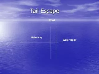
Tail Escape. Road. Waterway. Water Body. Tail escape is a structure constructed at the end of a waterway to evacuate the water to a water body.

Tail Escape
E N D
Presentation Transcript
Tail Escape Road Waterway Water Body
Tail escape is a structure constructed at the end of a waterway to evacuate the water to a water body. • Tail escape consists of a well where its crest level at the high water level. It is also equipped with an orifice at its bottom to evacuate all the water in 24 hrs if necessary. • A pipe evacuates the water to the water body under the road.
Road D d do Tail Escape
Hydraulic Design • Hydraulic design of the tail escape consists of three parts: 1. Automatic evacuation (Weir) 2. Controlled evacuation (Orifice) 3. Discharging to Sea (Pipe)
Automatic Evacuation: The excess water is evacuated over the weir's crest. The maximum acceptable rise in water level is 25 cm. the discharge of water over the weir can be calculated as follows: Qw = Ts . h . Vs
Where: Qw is the weir’s discharge in m3/sec, Ts is the top width of the water surface in m, h is the rise in water level =0.25 m, Vs is the surface water velocity in m/sec. Vs = 1.17 vw
Ts Where vw is the mean water velocity of the water way. 25 cm H.W.L.
To design the size of the well, the weir equation is used, Where Cd is the discharge coefficient = 0.55, B is the crest length, and
2. Controlled Evacuation: Orifice is designed to evacuate the waterway in 24 hrs. The following equation is used to determine the size of the orifice, Where: T is the time to empty the waterway = 24 . 60 .60 sec
L is the waterway length in m, be is the waterway average width in m, y is the depth of the waterway, Cd is the discharge coefficient = 0.6 Ts H.W.L. be y b
a is the area of the orifice in m2 and, Notice: The orifice is equipped with a gate so the water in the waterway can be used for any purpose. The gate is open to evacuate the water if needed.
3. Pipe: The pipe is designed to the maximum discharge for emergency as: Where: Qp is the pipe discharge, Qo is the orifice discharge
Where: And, Where Vp is the pipe velocity (2.0 m/sec) and D is the pipe diameter.
Example: A tail escape is required to be constructed at the end of a waterway according to the following data; Q = 4.6 m3/sec, Waterway length = 3000 m, Vc=0.45 m/sec 7.6 m 1.8 m 5.8 m 4 m
Sol. a. Automatic evacuation Qw= 7.6 * 0.15 * (1.17*0.45) = 0.6 m3/sec 0.6 = (2/3)*0.55*B*(√2*9.81)*(0.15)1.5 B = 6.36 m D = 2.7 m b. Controlled Evacuation T = 24*60*60
a = 0.2 m2 do= 0.5 m c. Pipe Qp=Qw+Qo Qo=0.6*0.2*(√2*9.81*2.05) = 0.76 m3/sec Qp= 1.36 m3/sec Assume Vp= 2 m/sec
1.36 = 2 * Ap D = 0.93 m take D = 1.0 m Vp= 1.73 m/sec