Download

1 / 15
150 likes | 296 Vues
NATIONAL TECHNICAL UNIVERSITY OF UKRAINE “THE KYIV POLITECHNIC INSTITUTE”. “ULTRASONIC SYSTEM OF DISTANT DETERMINATION COORDINATES”. THE DEVISES FACULTE GROUP ПК-81м SERGII GUDZ. ULTRASONIC SYSTEMS. INTRODUCTION.

E N D
NATIONAL TECHNICAL UNIVERSITY OF UKRAINE “THE KYIV POLITECHNIC INSTITUTE” “ULTRASONIC SYSTEM OF DISTANT DETERMINATION COORDINATES” THE DEVISES FACULTE GROUP ПК-81м SERGII GUDZ
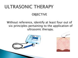
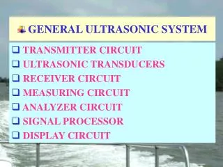
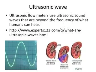
INTRODUCTION • This module presents an introduction to the ultrasonic system of distant determination coordinates. • Ultrasonic system uses high frequency sound energy to conduct examinations and make measurements. • Ultrasonic examinations can be conducted on a wide variety of material forms including castings, forgings, welds, and composites.
The transducer is capable of both transmitting and receiving sound energy. Ultrasound is generated with a transducer. ULTRASOUND GENERATION A piezoelectric element in the transducer converts electrical energy into mechanical vibrations (sound), and vice versa.
PRINCIPLES OF ULTRASONIC INSPECTION • Ultrasonic waves are introduced into a material where they travel in a straight line and at a constant speed until they encounter a surface. • At surface interfaces some of the wave energy is reflected and some is transmitted. • The amount of reflected or transmitted energy can be detected and provides information about the size of the reflector. • The travel time of the sound can be measured and this provides information on the distance that the sound has traveled.
0 2 4 6 8 10 TEST TECHNIQUES - PULSE-ECHO • In pulse-echo testing, a transducer sends out a pulse of energy and the same or a second transducer listens for reflected energy (an echo). • The amount of reflected sound energy is displayed versus time, which provides the inspector information about the size and the location of features that reflect the sound. f initial pulse back surface echo crack echo
TEST TECHNIQUES – NORMAL AND ANGLE BEAM • In normal beam testing, the sound beam is introduced into the test article at 90 degree to the surface. • In angle beam testing, the sound beam is introduced into the test article at some angle other than 90.
1 2 2 1 IP IP FWE FWE BWE BWE DE 0 2 4 6 8 10 0 2 4 6 8 10 TEST TECHNIQUES – CONTACT VS IMMERSION • In contact testing (shown on the previous slides) a couplant such as water, oil or a gel is applied between the transducer and the part. • With immersion testing, an echo from the front surface of the part is seen in the signal but otherwise signal interpretation is the same for the two techniques. IP = Initial Pulse FWE = Front Wall Echo DE = Defect Echo BWE = Back Wall Echo
TRANSDUCERS • Transducers are manufactured in a variety of forms, shapes and sizes for varying applications. • Transducers are categorized in a number of ways which include: • - Contact or immersion • - Single or dual element • - Normal or angle beam • In selecting a transducer for a given application, it is important to choose thedesired frequency, bandwidth, size.
CONTACT TRANSDUCERS Contact transducers are designed to withstand rigorous use, and usually have a wear plate on the bottom surface to protect the piezoelectric element from contact with the surface of the test article. Many incorporate ergonomic designs for ease of grip while scanning along the surface.
CONTACT TRANSDUCERS • A way to improve near surface resolution with a single element transducer is through the use of a delay line. • Delay line transducers have a plastic piece that is a sound path that provides a time delay between the sound generation and reception of reflected energy. • Interchangeable pieces make it possible to configure the transducer with insulating wear caps or flexible membranes that conform to rough surfaces.
Signal Amplitude Signal Amplitude Time Time DATA PRESENTATION - A-SCAN • A-scan presentation displays the amount of received ultrasonic energy as a function of time. • Relative discontinuity size can be estimated by comparing the signal amplitude to that from a known reflector. • Reflector depth can be determined by the position of the signal on the horizontal sweep.
DATA PRESENTATION - B-SCAN • B-scan presentations display a profile view (cross-sectional) of a test specimen. • Only the reflector depth in the cross-section and the linear dimensions can be determined. • A limitation to this display technique is that reflectors may be masked by larger reflectors near the surface.
DATA PRESENTATION - C-SCAN • The C-scan presentation displays a plan type view of the test specimen and discontinuities. • C-scan presentations are produced with an automated data acquisition system, such as in immersion scanning. • Use of A-scan in conjunction with C-scan is necessary when depth determination is desired. Photo of a Composite Component C-Scan Image of Internal Features