Download

1 / 29
610 likes | 2.68k Vues
CENTRIFUGAL PUMP CHARACTERISTICS. CE 370. Types of Pumps. There are different types of pumps which are used for different purposes in water and wastewater transportation: Low-lift pumps are used to lift water and wastewater from a source to the treatment plants,

E N D
Types of Pumps There are different types of pumps which are used for different purposes in water and wastewater transportation: • Low-lift pumps are used to lift water and wastewater from a source to the treatment plants, • high-service pumps are used to pump water and wastewater under pressure, • Booster pump are used to increase pressure in water distribution systems, • Well-pumps are used to lift water from wells, • Recirculation pumps are used to recirculate water within a system, and • Pumps are also used to feed chemicals, sample water and wastewater and fight fires.
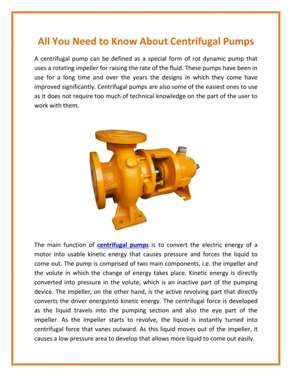
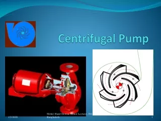
Centrifugal Pumps Centrifugal pumps are commonly used in the field of water and wastewater for a variety of applications: • Lift and transport water, • Move sludge, • Well pumping, and • Wastewater lift stations. Centrifugal pumps are common ones due to: • Simplicity • Compactness • Low-cost • Ability to operate under wide conditions. Centrifugal pumps are mainly composed of : • The impeller, which is a rotating member with vanes • Surrounding case, see figure.
Centrifugal Pumps The name "Centrifugal" is driven from the force, the pump depends on, to transport water. That force is the centrifugal force. The impeller can be: • Closed, which is used to transport water and • Open, which is used to transport wastewater containing suspended solid. How centrifugal pumps operate?? • The impeller is driven at high rotational speed, • The impeller throws the water into the volute • The water channels through the nozzle to the discharge.
Pump Head-Discharge Curve Pump manufacturers establish head-discharge curves at constant impeller speed and based on experiments. The head given in those curves represent the head at a given discharge when the inlet static water level is at the elevation of the pump centerline and excluding the head losses developed in the suction and discharge pipelines, see figure. The figure shows the following: • Discharge is controlled by a valve, • Discharge pressure is measured by a pressure gauge, and • Discharge flow rate is measured by a flow meter. In the mean time, power input and efficiency of the pump are measured and determined.
Pump Head-Discharge Curve When valve is closed, the discharge pressure reaches a value called "the shutoff pressure". As the valve is gradually opened, the discharge flow will increase and the pump head will decrease, see figure. The figure shows the pump efficiency increases with the increase in discharge flow, until it reaches an optimum value and starts to decrease. Centrifugal pumps are made to operate close to the optimum efficiency. When pumps are operated beyond optimum conditions, problems such as cavitation and water hammering start to occur. When pumps are operated near to shutoff pressure, problems such as vibration and hydraulic losses could happen. Operating the pump at 60 to 120 percent of the efficiency was considered to be a good practice.
Pump Characteristics Usually manufacturers produce characteristics curves for pumps with different impeller diameter and operating speeds. For a given impeller diameter running at different speeds, the discharge is directly proportional to to the speed, head is proportional to the square of speed, and power input is proportional to the cube of the speed as shown in the following equations: where: Q = discharge, gallons per minute (liters per second H = head, feet (meters) Pi = power input, horsepower (kilowatts).
Pump Characteristics If the pump operates at constant speed but at different impeller diameter, the effect of discharge, head and power input becomes as follows: where D = impeller diameter, inches (centimeters)
Power and Efficiency The power input of a pump is equal to the work done per unit time in lifting water to a higher point. Discharge and head can be related to power input by the following equation: where Po = power output, horsepower Q = discharge, gallons per minute H = head, feet w = unit weight of water = 8.34 lb/gal 550 = foot pounds / second per horsepower 60 = seconds per minute 3960 = 550 60 / 8.34
Power and Efficiency In metric units, the power output of a pump is: where Po = power output, kilowatts (kilonewton meter per second) Q = discharge, liters per second H = head, meters w = unit weight of water = 0.0098 kN per liter
Power and Efficiency The efficiency of the pump is the ratio of the power output to the power input and can be expressed in the form of: where Ep = pump efficiency, dimensionless Pi = power input, horsepower (kilowatts) Po = power output, horsepower (kilowatts).
System Characteristics When a pump is put into service in a water distribution system, its flow of discharge faces resistance due to: • Static head and • Friction head loss Static head is the difference in elevation between suction and discharge points. If a simple water system was considered, see the following figure. • Water is pumped from an inlet point • Water is discharged either into • elevated storage (outlet 1) • load center (outlet 2) • both (outlets 1 and 2)
System Characteristics If water is discharged from outlet 1, then the system will have the hydraulic grade line 1, while if water is discharged from outlet 2 then the system will be described by the hydraulic grade line 2. The head-discharge curves for the system are shown in the following figure.
Constant-Speed Pumps A constant-speed pump operates at a head-discharge point defined by the intersection of the pump head-discharge curve and the system head-discharge curve, see the following figure.
Constant-Speed Pumps • When the entire water is pumped to the elevated tank, the constant-speed pump will operate at point A, while when the water was entirely withdrawn from outlet 2, the pump will operate at point B. • The curve shows that Q2 > Q1 why? Because the operating pressure (static and friction head losses) at point B is less than that at point A. • In small water systems, pumping stations may consist of two constant-speed pumps that operate intermittently. Water is pumped directly to an elevated tank, which in turn supplies the distribution system. Pump operation is controlled by the level of water in the elevated tank. • In larger systems installation of al least three pumps is desirable in order to cover the extremes in water demand and to provide a standby pump. Water is pumped directly to the distribution system and elevated tanks are connected to the piping system. • Parallel operation of constant-speed pumps is shown in the following figure.
Constant-Speed Pumps Pumps 1 and 2 are identical, while pump 3 has a greater capacity and higher shutoff head. The pumps are operated individually or in combination based on the water demand. When two or more pumps operate at one time, the combined head-discharge curve can be obtained by adding the rates of discharge at the same head of the individual curve.
Variable-Speed Pumps In cases where variable discharge rates are required, discharge of pumps running at constant-speed can be controlled by using a valve at the pump outlet. Restricting discharge causes the impeller to recirculate water in the casing, reducing the efficiency and damaging the pump bearings and impeller. In order to maintain constant pump discharge head over a wide rage of flow rates, variable-speed pumps are used. Head-discharge curves for a pump operating at two impeller speeds are shown in the following figure.
Variable-Speed Pumps The pump can operate on an infinite number of curves between the minimum and maximum speeds, the dashed lines are of equal efficiencies. The demand-head curve is shown in the following figure.
Variable-Speed Pumps The curve illustrates the required boost head by the pump versus flow demand of the system. As water demand increases, pump discharge pressure decreases, so impeller speed increases. On the other hand, as water demand decreases, pump discharge pressure increases, so impeller speed decreases. Combining the head-discharge and head-demand curves will result in producing the following figure. Also the speed and efficiency curves can be plotted.
Variable-Speed Pumps At low water demand rates, the variable-speed drive should be prevented from running at very low speeds. So, when water demand is less than the minimum rate, pumps are designed to recirculate water through the pump in order to prevent the pump from damage. The recommended minimum discharge rate is between 25 and 35 per cent of the pumping rate at the best operating efficiency. The recirculation techniques are shown in the following figure.
Variable-Speed Pumps • The first system uses a flow meter to operate a modulating valve in a by-pass to maintain a nearly constant flow through the pump when the demand is less than the minimum recommended rate of discharge. • The second system employs a back-pressure regulating valve in the by-pass. This system can be used if the discharge curve turns downward. Variable-speed pumps operate in combination and may function by either load sharing or staggered operation. • In load sharing, all pumps operate at the same speed and discharge at equal rates. In staggered operation, one or more of the pumps operate at optimum efficiency (constant speed) while only one pump is varied to meet changing demand. • Variable-speed pumps can also be used in combination with constant-speed pumps.