Timing Recovery and Protocols in Peer-to-Peer Data Transmission
250 likes | 381 Vues
This chapter focuses on timing recovery for synchronous services in peer-to-peer networks. It discusses the impact of network delays, jitter, and packet transfer variations on real-time applications such as voice, audio, and video. The use of equally spaced packets, playout buffers, and the importance of synchronizing clocks between transmitters and receivers are examined to maintain the integrity of data streams. Additionally, it addresses TCP's reliable stream service, including selective repeat ARQ, sequence numbers, and graceful connection closures using the three-way handshake mechanism.

Timing Recovery and Protocols in Peer-to-Peer Data Transmission
E N D
Presentation Transcript
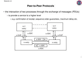
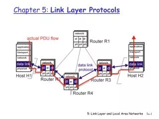
Chapter 5Peer-to-Peer Protocols and Data Link Layer Timing Recovery
Timing Recovery for Synchronous Services Network output not periodic Synchronous source sends periodic information blocks Network • Applications that involve voice, audio, or video can generate a synchronous information stream • Information carried by equally-spaced fixed-length packets • Network multiplexing & switching introduces random delays • Packets experience variable transfer delay • Jitter (variation in interpacket arrival times) also introduced • Timing recovery re-establishes the synchronous nature of the stream
Packet Arrivals Packet Playout Playout Buffer Packet Arrivals Sequence numbers help order packets Packet Playout Tmax Introduce Playout Buffer • Delay first packet by maximum network delay • All other packets arrive with less delay • Playout packet uniformly thereafter
Arrival times Time Send times Receiver too slow; buffer fills and overflows Playout times Tplayout time Receiver too fast buffer starvation Receiver speed just right Time Time Many late packets Tplayout Tplayout time time Playout clock must be synchronized to transmitter clock
Buffer for information blocks Playout command Error signal + Adjust frequency Smoothing filter Add t3 t1 t4 t2 - Timestamps Counter Clock Recovery Timestamps inserted in packet payloads indicate when info was produced Recovered clock • Counter attempts to replicate transmitter clock • Frequency of counter is adjusted according to arriving timestamps • Jitter introduced by network causes fluctuations in buffer & in local clock
Synchronization to a Common Clock Receiver Transmitter M M Network fs fr fn Network clock M=#ticks in local clock In time that net clock does N ticks f=fn-fs=fn-(M/N)fn N ticks fr=fn-f fn/fs=N/M N ticks • Clock recovery simple if a common clock is available to transmitter & receiver • E.g. SONET network clock; Global Positioning System (GPS) • Transmitter sends f of its frequency & network frequency • Receiver adjusts network frequency by f • Packet delay jitter can be removed completely
Example: Real-Time Protocol • RTP (RFC 1889) designed to support real-time applications such as voice, audio, video • RTP provides means to carry: • Type of information source • Sequence numbers • Timestamps • Actual timing recovery must be done by higher layer protocol • MPEG2 for video, MP3 for audio
Chapter 5Peer-to-Peer Protocols and Data Link Layer TCP Reliable Stream Service & Flow Control
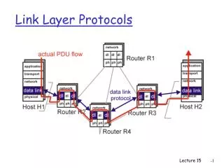
TCP Reliable Stream Service TCP transfers byte stream in order, without errors or duplications Application Layer writes bytes into send buffer through socket Application Layer reads bytes from receive buffer through socket Write 45 bytes Write 15 bytes Write 20 bytes Read 40 bytes Read 40 bytes Application layer Transport layer Segments Transmitter Receiver Receive buffer Send buffer ACKs
TCP ARQ Method • TCP uses Selective Repeat ARQ • Transfers byte stream without preserving boundaries • Operates over best effort service of IP • Packets can arrive with errors or be lost • Packets can arrive out-of-order • Packets can arrive after very long delays • Duplicate segments must be detected & discarded • Must protect against segments from previous connections • Sequence Numbers • Seq. # is number of first byte in segment payload • Very long Seq. #s (32 bits) to deal with long delays • Initial sequence numbers negotiated during connection setup (to deal with very old duplicates) • Accept segments within a receive window
Transmitter Receiver Send Window Receive Window Slast + Wa-1 Rlast + WR – 1 Rlast ... ... ... Rnext Rnew octets transmitted & ACKed Slast Slast + Ws – 1 Srecent Rlast highest numbered octet not yet read by the application Rnext next expected byte Rnew highest numbered byte received correctly Rlast+WR-1 highest-numbered byte that can be accommodated in receive buffer Slast oldest unacknowledged byte Srecent highest numbered transmitted octet Slast+Wa-1 highest-numbered byte that can be transmitted Slast+Ws-1 highest-numbered byte that can be accepted from the application
TCP Connections • TCP Connection • One connection each way • Identified uniquely by Send IP Address, Send TCP Port #, Receive IP Address, Receive TCP Port # • Connection Setup with Three-Way Handshake • Three-way exchange to negotiate initial Seq. #’s for connections in each direction • Data Transfer • Exchange segments carrying data • Graceful Close • Close each direction separately
Three Phases of TCP Connection Host A Host B SYN, Seq_no = x SYN, Seq_no = y, ACK, Ack_no = x+1 Three-way Handshake Seq_no = x+1, ACK, Ack_no = y+1 Data Transfer FIN, Seq_no = w ACK, Ack_no = w+1 Graceful Close Data Transfer FIN, Seq_no = z ACK, Ack_no = z+1
1st Handshake: Client-Server Connection Request Initial Seq. # from client to server SYN bit set indicates request to establish connection from client to server
2nd Handshake: ACK from Server ACK Seq. # = Init. Seq. # + 1 ACK bit set acknowledges connection request; Client-to-Server connection established
2nd Handshake: Server-Client Connection Request Initial Seq. # from server to client SYN bit set indicates request to establish connection from server to client
3rd Handshake: ACK from Client ACK Seq. # = Init. Seq. # + 1 ACK bit set acknowledges connection request; Connections in both directions established
TCP Data Exchange • Application Layers write bytes into buffers • TCP sender forms segments • When bytes exceed threshold or timer expires • Upon PUSH command from applications • Consecutive bytes from buffer inserted in payload • Sequence # & ACK # inserted in header • Checksum calculated and included in header • TCP receiver • Performs selective repeat ARQ functions • Writes error-free, in-sequence bytes to receive buffer
Data Transfer: Server-to-Client Segment 12 bytes of payload Push set 12 bytes of payload carries telnet option negotiation
Graceful Close: Client-to-Server Connection Client initiates closing of its connection to server
Graceful Close: Client-to-Server Connection ACK Seq. # = Previous Seq. # + 1 Server ACKs request; client-to-server connection closed
Send Window Receive Window Slast + WA-1 WA ... ... ... Rnew Rlast Rlast + WR – 1 Slast Slast + Ws – 1 Srecent Flow Control • TCP receiver controls rate at which sender transmits to prevent buffer overflow • TCP receiver advertises a window size specifying number of bytes that can be accommodated by receiver WA = WR – (Rnew – Rlast) • TCP sender obliged to keep # outstanding bytes below WA (Srecent - Slast) ≤ WA
Host A Host B t0 Seq_no = 1, Ack_no = 2000, Win = 2048, No Data t1 Seq_no = 2000, Ack_no = 1, Win = 1024, Data = 2000-3023 t2 Seq_no = 3024, Ack_no = 1, Win = 1024, Data = 3024-4047 t3 Seq_no = 1, Ack_no = 4048, Win = 512, Data = 1-128 t4 Seq_no = 4048, Ack_no = 129, Win = 1024, Data = 4048-4559 TCP window flow control
TCP Retransmission Timeout • TCP retransmits a segment after timeout period • Timeout too short: excessive number of retransmissions • Timeout too long: recovery too slow • Timeout depends on RTT: time from when segment is sent to when ACK is received • Round trip time (RTT) in Internet is highly variable • Routes vary and can change in mid-connection • Traffic fluctuates • TCP uses adaptive estimation of RTT • Measure RTT each time ACK received: n tRTT(new) = tRTT(old) + (1 – ) n • typical
RTT Variability • Estimate variance 2 of RTT variation • Estimate for timeout: tout = tRTT + k RTT • If RTT highly variable, timeout increase accordingly • If RTT nearly constant, timeout close to RTT estimate • Approximate estimation of deviation dRTT(new)= dRTT(old) + (1-) | n - tRTT | tout = tRTT + 4 dRTT