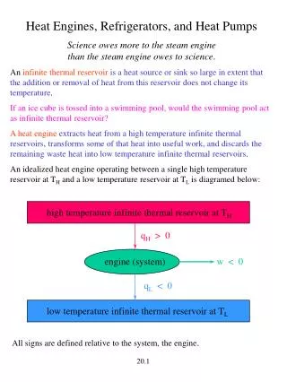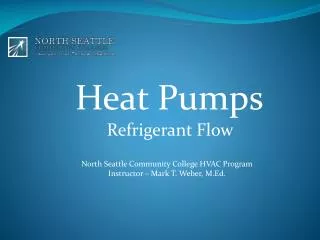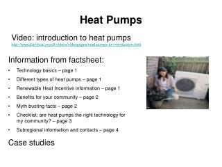
HEAT PUMPS
HEAT PUMPS. CPLE. Heat Pump CPLE. 10 S.E.E.R. Low pressure control Accumulator Check-flow rater expansion device Defrost controls. Nomenclature. CPLE. 18. 1. LOUVERED SERIES. VOLTAGE DESIGNATOR. 10 SEER CONDENSING. 1 = 208-230/1/60. HEAT PUMP. 3 = 208/230/3/60. NOMINAL CAPACITY.

HEAT PUMPS
E N D
Presentation Transcript
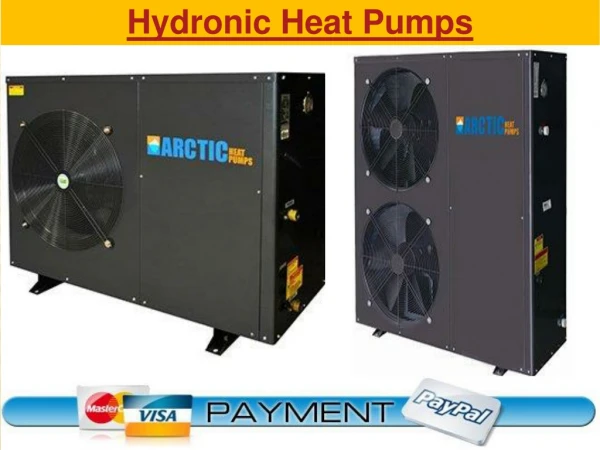
Heat Pump CPLE • 10 S.E.E.R. • Low pressure control • Accumulator • Check-flow rater expansion device • Defrost controls
Nomenclature CPLE 18 1 LOUVERED SERIES VOLTAGE DESIGNATOR 10 SEERCONDENSING 1 = 208-230/1/60 HEAT PUMP 3 = 208/230/3/60 NOMINAL CAPACITY 18 = 1-1/2 TONS 24 = 2 TONS 30 = 2-1/2 TONS 36 = 3 TONS 42 = 3-1/2 TONS 48 = 4 TONS 60 = 5 TONS
SETTING OF THE UNIT • Unobstructed condenser air inlet and discharge • 10 inches minimum air clearance on all sides • 18 inches clearance at the service access • Unit to be mounted solid level foundation • Make sure rooftop application can handle the weight
ELECTRICAL SERVICE • Unit rating plate will list electrical data for proper size of electrical service • Make owner familiar with location of the over • 18 gauge wire is needed for 24 volt control wiring
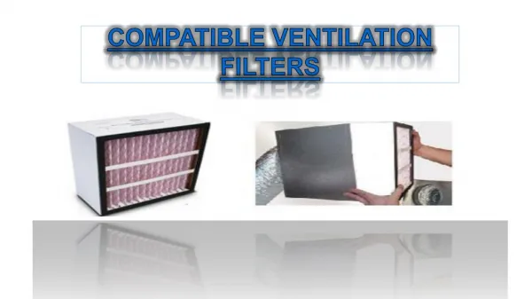
REFRIGERANT TUBING USE ONLY REFRIGERANT GRADE COPPER INDICATED IN TABLE 1 SUCTION LINE INSULATION IS NECESSARY TO PRESENT CONDENSATION 3/8 WALL THICKNESS OF ARMFLEX IS SATISFACTORY
BRAZING THE LINE SET • Tubing should be cut with a good tubing cutter • Clean off any burrs • Wrap a wet rag or use a thermal paste around a service valve to prevent overheating • Trickle a small amount of nitrogen through the line set • Braze with silver solder
LEAK TESTING • Visually check all solder joints with an inspection mirror • Add a trace amount of R22 and then fill line with 200 psig of dry nitrogen • Test with soap bubbles or electronic leak detector • If there are no leaks vacuum line set to 500 microns and hold for 30 minutes
SYSTEM CHARGE • System comes charged for 15 foot of line set and matching evaporator • Adjust the charge for every additional foot of line set(see chart) • Systems with over 50 foot line set may require an oil charge adjustment • Adjust the charge by the Superheat Method (see video)
Scroll Compressors should neverbe pumped down into a vacuum .This could could cause internal arching and cause the compressor to fail.
The Reversing Valve Is Energized In The Cooling And Defrost Modes Only
Pilot Valve Solenoid w/feeder tubes
Hot Gas Discharge tube Pilot Valve Tubes True Suction tube
INSTALLATION LOCATION 10 TO 12 INCHES FROM WALLS OR OBSTRUCTIONS IF THERE IS AN OVERHANG….. SHOULD BE AT LEAST 36 INCHES CLEARANCE UNIT IS TO BE MOUNTED ON A SOLID, LEVEL FOUNDATIONS ELECTRICAL • ALL WIRING MUST BEIN ACCORDANCE WITH THE NATIONAL ELECTRICAL CODE • RATING PLATE ON THE CONDENSING UNIT LISTS ELECTRICAL DATA NECESSARY FOR THE SELECTION OF PROPER SIZE ELECTRICAL SERVICE AND OVER-CURRENT PROTECTION • CONTROL WIRING REQUIRES A 24 VOLT MINIMUM 25 VA SERVICE FROM THE INDOOR TRANSFORMER ……………... 18 GAUGE WIRE MUST BE USED
TEMPERTURE RISE METHOD CFM = KW x 3413 TEMPERATURE RISE x 1.08 where : KW = The indoor section's measured input power = Volts x Amps and : Volts = The measured Volts at the Indoor Section Amps = The measured Amps at the indoor Section Temp. Rise = The temperature of the supply air minus the temperature of the return air 3413 = BTU per KW 1.08 = specific heat air constant e.g. : The input power to the indoor section = 10 KW The Temperature Rise = 20o F CFM = 10 x 3413 = 1580
Verifying proper air flow • Set thermostat to emergency heat mode. Call for heat. • Measure DT @ indoor coil • Measure Electric Heat volts & amps • BTU = Watts (Volts X Amps) X 3.413 • CFM = BTU / (DT X 1.08)
All Fuel Board • Goodman Part # AFE 18-60 • Primary Functions • Control Inputs • Control Outputs • Normal Operation • Outdoor Thermostat Mode • Control Environment
Primary Functions • Interface Between a Heat Pump Thermostat and a Heat Pump and a Fossil Fuel Furnace • Option for an Outdoor Thermostat • Compressor Short Cycling Prevention
Normal Operation • 1st Stage Cooling from Thermostat Operates the Heat Pump Compressor • 2nd Stage Cooling or an Emergency Heat Call Operates the Fossil Fuel Furnace & Disables Compressor • Timer Prevents Compressor from Operating for 120 Seconds from De-Activation
Control Inputs • “R” - Source is Furnace “R” Terminal • Distributes “R” to Heat Pump & Thermostat • “C” - 24VAC Common ; Source is Furnace • Distributes “C” to Heat Pump & Thermostat • “O” - Reversing Valve Routed to Heat Pump • “E”- Emergency drops out heat pump via K2 contact energizing W2 gas furnace heat • “W2”- 2nd Stage Call for Heat • Identical to Emergency Heat ; Connected to Same on Control
Control Outputs • Furnace “W” - Heat Pump “W2/OT-NO” • Furnace “G” - T-Stat Input for High Speed Fan • Heat Pump “O” - Reversing Valve Output • Heat Pump “Y” - Heat Pump Compressor Call
Control Outputs Continued... • Heat Pump “OT-NC” - Connects to Heat Pump “Y” thru N.C. Relay K2 and N.O. Relay K3 • Determines if Heat Pump Will Run When “Y” Call is Received from Thermostat • “OT-C” - Common Terminal for Outdoor Thermostat • “BREAK FOR ODT” Tab must be removed
Outdoor Thermostat Mode • Provision for SPDT Outdoor Thermostat • Outdoor Thermostat Must be Connected to the OT-NC & OT-C Terminals • Determines Whether Heat Pump or Furnace will Run in 1st Stage Heating. • The “BREAK FOR ODT” Must be Removed Before Connecting the Outdoor Thermostat
any questions? Thank you!