Comprehensive Overview of PDM Junction Block and Wiring Configurations for Pre-07 and 07-Up Models
180 likes | 427 Vues
This document provides a detailed outline of the junction blocks and wiring configurations for both pre-07 and 07-up models. It covers the specifications for MEGA FUSE connections, chassis PDM options, and various electrical components such as fans, heaters, and ignition systems. Included are fuse positions and their unique variations based on the engine type and brake system, ensuring a thorough understanding of the electrical architecture in these vehicles. This guide serves as a crucial resource for technicians working on these models.

Comprehensive Overview of PDM Junction Block and Wiring Configurations for Pre-07 and 07-Up Models
E N D
Presentation Transcript
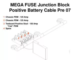
MEGA FUSE Junction BlockPositive Battery Cable Pre 07 1 Chassis PDM - 125 Amp 2 Chassis PDM - 125 Amp 3 Toeboard Positive Stud - 150 Amp “Cab” PDM 4 Spare 4 3 2 1
Battery 1 2 4 3 5 Engine PDM - 200 Amp Chassis PDM Pos 2 - 125 Amp Chassis PDM Pos 1 - 125 Amp Toeboard Positive Stud - 150 Amp “Cab” PDM Spare Location MEGA FUSE Junction BlockRear of Battery Box 07 & up
BAT - BAT + P16 P11 P18 P12 P15 P17 CAB PDM 07 & up
RR Htr EXM1 TCU Htr Pump Adj Pedal CHM Cr Arms BHM EXM1 ABS ECU Spare EXM1 ICU CHM Radio BHM CHM BHM Stwell Htr BHM EXM2 EXM2 Spare Cab PDM EXM2 BHM IGN VCU CHASSIS PDM Pre 07 Note that fuse positions varies (pre 07 only) based on engine make and type of brakes
EXM2 F1 EXM2 F9 EXM1 F15 EXM1 F2 CHM F10 EXM2 F16 Ex Door F21 Spare F18 Spare F17 CHM F3 ABS F11 Hydromax F22 CHM F4 Cool Htr F12 Wiper Lo CB18 ICU3 F23 Ign Sw F5 Wiper Motor Lo R2 Wiper Motor Hi R1 Wiper Motor Hi CB6 BHM F7 EXM1 F13 BHM F19 BHM F24 BHM F8 Adj Petals F14 Radio/Diag F20 BHM F25 Spare R2 CHASSIS PDM 07 & up
Lug Box F15 AGS F12 Cross A F9 Hyd ABS Lockout R4 Elect Fan Clutch Ignition R3 Ignition R2 Hyd DV2 F14 AGS F11 CPC F8 12V Pwr F13 TCM F10 Hyd Pump F7 MCM M3 Ignition R1 Spare F6 Eng Ign F3 Fuel Heater M2 Spare F5 TCM Ign F2 Defroster Blower M1 RollBack F4 Fan Cth F1 Engine PDM 07 & up R1 Controls Red Fuses R2 Controls Green Fuses R3 Controls Fuse F1
Chassis Module Ignition Power Powered by General IGN ECU IGN NOx Sensor ECU Bat ECU IGN ABS Ign ABS Bat ABS Bat ECU IGN ** W/W Low Battery Power W/W Lo Relay Power ECU Bat BHM BHM Rollback Firewall Module General IGN Fan Clutch W/W Hi W/W Hi General IGN General IGN ECU Bat 250 Amps CHM CHM CHM ICU Radio/Diag Ign Sw Engine Module DEF Line Heat Fan Clutch ECM Ign ECM Bat Fuel Heater EXM EXM EXM Auxiliary Func. Range Inhibit Adjustable Pedals 2 Way Radio ** Dash Power Plug Line Htr NOx In NOx Out DCU Ign DCU Bat Fuel Htr Cross Arm Ext Door HTD DV2 BHM BHM BHM Spare Blower Mtr Blower Mtr TCM Ign TCM Bat HTD DV2 Webasto Lug Box 175 Amps ** Not used at this time 125 Amps 2010 Fender PDM Change G06-73427
C2 MODULE PINOUT BHM
BHM 07 & up Emergency door buzzer Booster pump and water valve Center defrost fan low Marker lamp Step well light
CHM pre 07 License plate light
CHM 07 & up W/S washer Left dash fan low Lift Door buzzer W/C lift interlock Rear wall heater high Park brake interlock solenoid Heated mirrors Left dash fan high Stop arm relay B/U alarm Rear wall heater low
J1939 Service Connector A = Ground B = +12 Volt (Unswitched) C = J1939 High (Yellow) D = J1939 Low (Green) E = J1939 Shield F = J1587 + (Green or Blue) G = J1587 – (Orange or White) H & J = OEM use E D C B F A J H G