Advanced Image Processing System with Clustered Data Logic
120 likes | 219 Vues
This system utilizes DSP and FPGA technologies for fast processing of image data with precise control logic for data clustering.

Advanced Image Processing System with Clustered Data Logic
E N D
Presentation Transcript
V5 cluster search DSPController USB Tx USB Rx DSPCore Cluster FIFO PC data ADC Data
HIP core State Machine From USB FIFO RD Register 1..N To USB FIFO WR SM control L0, C0 L0,C0 Ctrl Line FIFO DSP Channel DATA DATA Raw/list data sel. SM control Cluster list FIFO Data out Cluster list
Mask for image processing P2,-2 P2,-1 P2,0 P2,1 P2,2 Line delay P1,-2 P1,-1 P1,0 P1,1 P1,2 Line delay P0,-2 P0,-1 P0,0 P0,1 P0,2 Line delay P-1,-2 P-1,-1 P-1,0 P-1,1 P-1,2 Line delay P-2,-2 P-2,-1 P-2,0 P-2,1 P-2,2 DataIn
Complete block diagram 2MB @400fps 32MB @400fps 32MB @400fps 32MB @400fps 2x 64MB @ N fps Pedestal memory Gain Bad pixel mask Noise (Optional) Reconstructed image Digital pixel 0 Matrix Data Cluster Matrix Size Charge Length Width +- DataIn Search Matrix Clustering Seed Logic x >> n ... Matrix Data Cluster validation Divide by 2^n Th Seed Th Neig. Bad pixel List Sub pixel (COG) L0 C0 Channel Controllogic
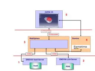
FPGA system Display jtag FPGA DDR3 Ethernet mController DDR3 DSP ADCs
Control packge received by the FPGA system ID refers to the submodule that the package is being sent. TYPE could be write register, read register, write data… Size is this package size, we want small for read/write register but big ones to download data such as the pedestal.
DSP Display jtag DSP DDR3 Bias & Clock DSPController DDR3 DSPCore ADCs
mController block diagram NiosII SG DMA TSE core DDR3 ctrl PIO
1 channel for the whole frame channel line4 Mask Seed logic line3 FIFO line2 DataIn MaskIn line1 line0 Control logic L0 C0 DataOut
Two channel system left channel line4 Mask Seed logic line3 FIFO line2 DataIn MaskIn line1 line0 L0 C0 Control logic DataOut Shared data right channel line4 Mask Seed logic line3 FIFO line2 DataIn MaskIn line1 line0 Control logic L0 C0 DataOut
Three or more channels left channel line4 Mask Seed logic line3 FIFO line2 DataIn MaskIn line1 line0 L0 C0 DataOut Controllogic center channel 1 .. n Shared data line4 Mask Seed logic line3 FIFO line2 MaskIn line1 DataIn line0 L0 C0 DataOut Control logic Shared data right channel line4 Mask Seed logic line3 FIFO line2 DataIn MaskIn line1 line0 L0 C0 DataOut Control logic