Download
1 / 26
260 likes | 294 Vues
F.W. Olin Center. Redesign of Structural Floor System with Emphasis on Vibration. Daniel Chwastyk – Structural Option. Thesis Presentation 2004. Presentation Outline. Existing building features Proposal and basis for proposal Redesign of floor framing Considerations raised by redesign

E N D
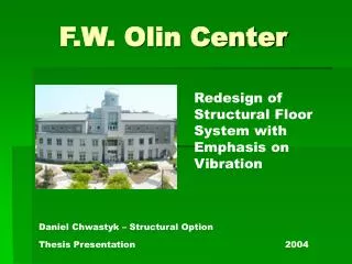
F.W. Olin Center Redesign of Structural Floor System with Emphasis on Vibration Daniel Chwastyk – Structural Option Thesis Presentation 2004
Presentation Outline • Existing building features • Proposal and basis for proposal • Redesign of floor framing • Considerations raised by redesign • Vibration check of floors • CM / Lighting Breadths • Conclusion
Existing Building Features • Owner:Union College • Architects / Primary Engineers:The Kostecky Group • General Contractor:G.C. Pike • Site Utilities:Friedman Fisher Associates, P.C. • Landscape Architects:The LA Group
Existing Building Features • Uses • 5 Story multi-use technology building • Science Center of Union College Size • 53,640 s.f. • $7.4 million dollar cost Architecture • 2 relatively symmetrical wings flanking a circular rotunda • Exterior – combination of earth and engineered materials
Existing building features Foundation • Continuous spread footings • Column footings under the few steel columns Structural • K-joist framing system • Non-composite steel system in several key rooms • CMU load bearing walls • Elevated floors are 3” concrete slab on form decking
Existing building features Lateral System • CMU shear walls • Seismic forces control • Base shear – 833 kips • Forces distributed based on the stiffness of the shear walls • Shear wall A was checked for strength 2262 psi (135.7 kips/60 in2) < 2500 psi
Proposal Vibration Vibration Vibration WEIGHT COST
Floor Comparison Composite Steel System Non Composite Steel System Concrete Pan Joist System One Way Concrete System
Floor Comparison Weight • One Way Concrete System (2.64 klf) • Concrete Pan Joist System (2.16 klf) • Non Composite Steel System (1.94 klf) • Composite Steel System (1.66 klf)
Floor Comparison • One Way Concrete System • Concrete Pan Joist System • Composite Steel System • Non Composite Steel System Other factors??
Redesign of Floor System • Applicable Code – IBC 2000 • Steel designed using ASCI Steel Design Manual • Live Loads • Taken from shop drawings • Dead Loads • Actual weight of steel and floor and 25 psi super-imposed load • Floor • 3” concrete • 20 Gauge UFX 36 form decking • 6x6 10/10 WWF
Redesign Of Floor System • Initial redesign based on gravity load • Beams were checked for deflection, and moment and shear capacities • Beams rest on 7 ½” x 7 ½” x ¾” bearing plates
Redesign Of Floor System • Cost considerations • Repetition of members • Availibility?? • Didn’t use any beams smaller than W 10
Redesign Of Floor System • Weight of Building • 10,000 kips original • 13,000 kips with new floor system • Checks needed due to weight increase • Shear • Foundations • Wall load
Braced Frames Reason for Investigation? Construction Time Design: Based on existing member sizes as well as a few calculations Check: Deflections of Frame C & D were checked in STAAD Maximum Deflection = 1.213”
Braced Frames Conclusions???
Vibration Check of Floors • Design guide 11 • Natural frequencies ( π → 1.4 π ) • Max allowable vibration for sensitive equipment • Δp – Deflection of the floor at midspan due to a 0.225 kip load • Moderate paced walking assumed: Uv = 5.5 kip*Hz2 Δp / fn ≤ V / Uv
Vibration Check of Floors Δp / fn ≤ V / Uv What to do????? Options to lower vibrations • Increase Member Size • Decrease Member Spacing • Require lower walking speed • Place sensitive equipment not at midspan
Vibration Check of Floors Laboratories needed to be redesigned Δp / fn ≤ V / Uv Pl3 ½ 96EI π/2 386EI 3.64 E-4 wl4
Vibration Check of Floors Telescope Room Design • Room was already designed with steel members, so a check is necessary • Telescope is permanently placed and sits atop two W 16x40 beams spaced 2 feet apart • Slow walking can be assumed in the confined area Vibrational velocity for this area = 86.4 µ in./sec
Cost Comparison Estimate created using ICE 2000 • Labor, Material and Equipment costs Increase of $90,934 Compared to $7.7 million building cost??
Lighting Breadth Second floor computer classroom lighting was altered. Done to… • Reduce to glare on the computers • Possibly lower the electrical load and costs • Existing fixtures: • 4 rows of recessed lensed troffers • 32 Watt T8 fluorescent lamps • (4 per fixture)
Lighting Breadth New fixture: Indirect/direct with 32 Watt fluorescent lamps Power density = 1.276 Watts Lightscape model
Conclusions • Vibrations were reduced • Costs increased slightly • Recommendation • The alternative framing system seems to be more beneficial in the F.W. Olin Center than the original system