Download
1 / 16
160 likes | 326 Vues
Bunch shorting scheme and scheme of extraction kicker in the ATF DR using RF technology. Vladimir Vogel KEK April 25, 2005. s z=4mm, D E=20Mev, T = 10 nSec, D f=450MHz. D E=1.5%. Septum, or small voltage kicker. 714 MHz. 714 MHz. 10 nSec. RF 11424MHz. E=E0+(20Mev +/- 2%)

E N D
Bunch shorting scheme andscheme of extraction kicker in the ATF DR using RF technology Vladimir Vogel KEK April 25, 2005
sz=4mm, DE=20Mev, T = 10 nSec, Df=450MHz DE=1.5% Septum, or small voltage kicker 714 MHz 714 MHz 10 nSec RF 11424MHz E=E0+(20Mev +/- 2%) 4s, p-p Load C and X band 10nSec, (5.0 nSec) 11.2 nSec E=E0(1+0.015)
Bunch length, s = 4mm 5s = 20mm
Accelerate voltage Accelerate phase 714 MHz 714 MHz Harmonic number Present Bunch length C band, 8mm-4mm 100kV 0 kV Start C band sz ~ (Urf)^0.5
L =1 m, P = 4 kW, U = 167 kV Single cell cavity, for 150kV,P=60 kW !
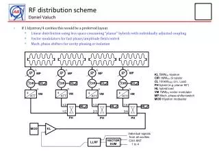
Low efficiency layout, Paver. = 600 kW e- 11ns Low reflection 10 MW load RF 1ns High group velocity C- band AC modulator, U=230kV, I=525A 377ns RF High group velocity X- band AC ~10MW 10 MW X- band Klystron Df = 4% HV 10 MW C - band Klystron Df = 8% 377*2820=1.063ms
High efficiency layout, Paver. = 68kW e- Low reflection 10 MW load 1MW 1MW 1MW 1MW 377ns RF High group velocity C-band and X-band AC ~10MW 10 MW +/-90 degree phase shifter Tsw. < 377ns HV 1 2 3 4 377*4=1508ns (377-15) ns delay line 11ns 3 db hybrid 40MW RF 10MW 10 MW Klystron C-bandDf = 8% HV 15ns 1MW Klystron X-bandDf = 4% 60 ns IGBT induction type modulator, U=230kV, I=350A
Propagation of TE01 and TE02 modes through cooper circular waveguide, D120mm x L110m. Experimental results: Loss: TE01 - 2.90% (theory 2.36% ) TE02 – 8.96% (theory 8.62%) TE01 efficiency 97.10 % TE02 efficiency 90.63% S.Kazakov, A.Lunin, 2003
X-band TW mixed-mode window Passband of X-band travelling-wave mixed-mode window S.Kazakov
X-band pillbox window Passband of X-band pillbox window S.Kazakov
4000mm U=230kV, I=350A, T=60nSec, Trise~60 nSec
ILC bunch spacing in DR = 11.2 (5.6) nS, DR circumference 9.52 (4.76) km • Four Structure, L=0.5 m, Vgr~0.15, a/l ~ 0.3, DE = 4*5 =20 Mev • Four Klystrons, pulse length~ 10 nSec, Df = 8%, Pout ~10 MW • Repetition rate (2.65/4) MHz, (with delay lines), Pav.=4*10kW • IGBT modulator for 4 klystrons, 230kV, 350A, Pav=60kW • DR one turn time ~ 34.7 uS, tdamp. ~ 25 mS, Ndr = 735*4, (LC X-band N = ~12 000, a/l=0.17)