Download
1 / 67
740 likes | 978 Vues
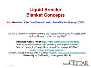
Liquid Breeder Blanket Concepts. One of a number of lectures given at the Institute For Plasma Research (IPR) at Gandhinagar, India, January 2007 Mohamed Abdou (web: http://www.fusion.ucla.edu/abdou/ ) Distinguished Professor of Engineering and Applied Science

E N D
Liquid Breeder Blanket Concepts One of a number of lectures given at the Institute For Plasma Research (IPR) at Gandhinagar, India, January 2007 Mohamed Abdou (web: http://www.fusion.ucla.edu/abdou/) Distinguished Professor of Engineering and Applied Science Director, Center for Energy Science and Technology (CESTAR) (http://www.cestar.seas.ucla.edu/) Director, Fusion Science and Technology Center (http://www.fusion.ucla.edu/) University of California, Los Angeles (UCLA) And Overview of the Dual-Coolant Lead-Lithium Blanket Concept (DCLL) Abdou Lecture 3
Liquid Breeder Blanket Concepts and Overview of the Dual-Coolant Lead-Lithium Blanket Concept (DCLL) Outline • Introduction to liquid breeder blankets and issues • Key aspects of the Design, Technical topics and Issues (e.g. MHD, insulation, tritium extraction and permeation, heat extraction and thermodynamic cycle, compatibility, etc) for various concepts: • Self-cooled cooled liquid metal (LM) concepts • Separately cooled liquid metal (LM) concepts • The Dual-Coolant Lead Lithium (DCLL) Blanket concepts • Molten salt self cooled and dual coolant concepts • DCLL R&D • Appendix examples of data (thermo physical properties for liquid breeders) Abdou Lecture 3
Liquid Breeders • Many liquid breeder concepts exist, all of which have key feasibility issues. Selection can not prudently be made before additional R&D and fusion testing results become available. • Type of Liquid Breeder: Two different classes of materials with markedly different issues. • Liquid Metal: Li, 83Pb 17Li High conductivity, low Pr number Dominant issues: MHD, chemical reactivity for Li, tritium permeation for LiPb • Molten Salt: Flibe (LiF)n· (BeF2), Flinabe (LiF-BeF2-NaF) Low conductivity, high Pr number Dominant Issues: Melting point, chemistry, tritium control Abdou Lecture 3
Liquid Breeder Blanket Concepts • Self-Cooled • Liquid breeder circulated at high speed to serve as coolant • Concepts: Li/V, Flibe/advanced ferritic, flinabe/FS • Separately Cooled • A separate coolant, typically helium, is used. The breeder is circulated at low speed for tritium extraction. • Concepts: LiPb/He/FS, Li/He/FS • Dual Coolant • First Wall (highest heat flux region) and structure are cooled with a separate coolant (helium). The idea is to keep the temperature of the structure (ferritic steel) below 550ºC, and the interface temperature below 480ºC. • The liquid breeder is self-cooled; i.e., in the breeder region, the liquid serves as breeder and coolant. The temperature of the breeder can be kept higher than the structure temperature through design, leading to higher thermal efficiency. Abdou Lecture 3
Liquid breeder blankets use a molten lithium-containing alloy for tritium breeding. The heat transport medium may be the same or different. Blanket - surrounds plasma • Functions of • Generic Blanket • Heat Removal • Tritium Production • Radiation Shielding Abdou Lecture 3
Advantages of Liquid Metal Blankets LM Blankets have the Potential for: • High heat removal • Adequate tritium breeding ratio appears possible without beryllium neutron multiplier in Li, PbLi (Pb serves as a multiplier in PbLi). (Note that molten slats, e.g flibe has beryllium part of the salt and generally requires additional separate Be.) • Relatively simple design • Low pressure, low pumping power (if MHD problems can be overcome) See BCSS for review of many possible blanket systems. Abdou Lecture 3
Flows of electrically conducting coolants will experience complicated magnetohydrodynamic (MHD) effects What is magnetohydrodynamics (MHD)? • Motion of a conductor in a magnetic field produces an EMF that can induce current in the liquid. This must be added to Ohm’s law: • Any induced current in the liquid results in an additional body force in the liquid that usually opposes the motion. This body force must be included in the Navier-Stokes equation of motion: • For liquid metal coolant, this body force can have dramatic impact on the flow: e.g. enormous MHD drag, highly distorted velocity profiles, non-uniform flow distribution, modified or suppressed turbulent fluctuations.
Main Issue for Flowing Liquid Metal in Blankets: MHD Pressure Drop Feasibility issue – Lorentz force resulting from LM motion across the magnetic field generates MHD retarding force that is very high for electrically conducting ducts and complex geometry flow elements Thin wall MHD pressure drop formula p, pressureL, flow lengthJ, current densityB, magnetic inductionV, velocity, conductivity (LM or wall)a,t, duct size, wall thickness Abdou Lecture 3
Inboard is the critical limiting region for LM blankets • B is very high! 10-12T • L is fixed to reactor height by poor access • a is fixed by allowable shielding size • Tmax is fixed by material limits Combining Power balance formula L With Pipe wall stress formula With thin wall MHD pressure drop formula (previous slide) gives: (Sze, 1992) Pipe stress is INDEPENDENT of wall thickness to first order and highly constrained by reactor size and power!
No pipe stress window for inboard blanket operation for Self-Cooled LM blankets (e.g. bare wall Li/V) (even with aggressive assumptions) U ~ 0.16 m/s Pmax ~ 5-10 MPa • Pipe stress >200 MPa will result just to remove nuclear heat • Higher stress values will result when one considers the real effects of: • 3D features like flow distribution and collection manifolds • First wall cooling likely requiring V ~ 1 m/s Unacceptable Marginal Allowable ARIES-RS ITER Best Possible DEMO Base Case for bare wall Li/V: NWL = 2.5 MW/m2 L = 8 m, a = 20 cm T = 300K Abdou Lecture 3
What can be done about MHD pressure drop? c represents a measure of relative conductance of induced current closure paths • Lower C • Insulator coatings • Flow channel inserts • Elongated channels with anchor links or other design solutions • Lower V • Heat transfer enhancement or separate coolant to lower velocity required for first wall/breeder zone cooling • High temperature difference operation to lower mass flow • Lower B,L • Outboard blanket only (ST) • Lower (molten salt) Break electrical coupling to thick load bearing channel walls Force long current path Abdou Lecture 3
Net JxB body force p = cVB2 where c = (tw w)/(a ) For high magnetic field and high speed (self-cooled LM concepts in inboard region) the pressure drop is large The resulting stresses on the wall exceed the allowable stress for candidate structural materials Perfect insulators make the net MHD body force zero Insulator coatings were proposed But insulator coating crack tolerance is found to be very low (~10-7). It appears impossible to develop practical insulators under fusion environment conditions with large temperature, stress, and radiation gradients Self-healing coatings have been proposed but none has yet been found (research is on-going) A perfectly insulated “WALL” can eliminate the MHD pressure drop. But is it practical? Conducting walls Insulated walls Lines of current enter the low resistance wall – leads to very high induced current and high pressure drop All currents must close in the liquid near the wall – net drag from jxB force is zero Abdou Lecture 3
Vanadium structure Lithium Li Secondary Shield Li Primary Shield Li Breeding Zone (Li flow) Reflector Primary shield Secondary shield Reflector Vanadium Structure Lithium Example of Self-Cooled Blanket :Li/Vanadium Blanket Concept Abdou Lecture 3
Self-cooled Lithium with Vanadium Alloy • Self-cooled Lithium with Vanadium Alloy Structure was the U.S. choice for a long time, because of its perceived simplicity. But no more. • Russia still has Li/V option (there is interest in some Japanese universities) • Li/V Conceptual Designs were developed in the US: • Blanket Comparison and Selection Study (BCSS 1983-84) • ARIES-RS (in the 1990’s) Abdou Lecture 3
Issues with the Lithium/Vanadium Concept Issues • Insulator • Insulator coating is required • Crack tolerance (10-7) appears too low to be achievable in the fusion environment • “Self-healing” coatings can solve the problem, but none has yet been found (research is ongoing) • Corrosion at high temperature (coupled to coating development) • Existing compatibility data are limited to maximum temperature of 550ºC and do not support the BCSS reported corrosion limit of 5mm/year at 650ºC • Tritium recovery and control • Li REACTIVITY with air and water is very serious; precludes use of water anywhere • Li/V was the U.S. choice for a long time, because of its perceived simplicity. But negative R&D results and lack of progress on serious feasibility issues have eliminated U.S. interest in this concept as a near-term option. Insulating layer Conducting wall Leakage current Electric currents lines Crack • Vanadium alloy development is very costly and requires a very long time to complete Abdou Lecture 3
Insulator coating main focus Li/V • Ideal coatings are the ideal solution to the MHD pressure drop problem • All surfaces covered by insulator coatings – AlN,YtO3, ErO3 • Self healing paradigm assumed where cracks and spalls are quickly healed • However, Tolerable crack fraction (assuming Li wetting) appears to be quite low, well below that achievable with real coatings • How well does the lithium penetrate small cracks and electrically contact the pressure bearing wall as a function of time? • What is the crack fraction, size, distribution as a function of time? • Can self-healing work? • US materials people pessimistic about self-healing, suggestion has been made to move to multi-layer insulating barriers – alternating layers of insulator and metallic protection layer • Metal layer seals underlying insulator so insulator cracks have no effect. • Thickness of metal layer will govern pressure drop Abdou Lecture 3
All tests with bare insulator in contact with Li showed immediate electrical shorts upon Li melting, and often removal of large areas of the coating.
Multiple Layer Insulating Barriers Coatings • Thin metal layer protects underlying insulator coating. • The layer must be thin to keep MHD pressure drop acceptable 10-100 microns. • Corrosion and integrity of this layer is an important potential issue. • Russian research in this area going on for several years, having difficulty achieving dense metallic layers on top of AlN insulator coatings by spraying technique • Considering separate metallic liners or baked on foils. Vitkovkski et al. FED, v. 61-62 (2002) Abdou Lecture 3
Other LM blanket issues:Pressure drop effect on flow balance • Changes in insulator can also have large effects on the flow balance between parallel channels. • Velocity varies linearly with the pressure difference, so v1/v2 = c2/c1 for thin walled channels. • This is a significant issue for liquid metal blankets, even if the overall pressure drop is acceptable. • It is desirable to choose and insulation scenario where small changes in insulation do not produce large changes in pressure drop. • Another possible mitigation technique is to force some degree of flow balancing by electrically connecting the channels in clever ways. Abdou Lecture 3
Other LM blanket issues:Velocity Profiles and Impact on Heat Transfer • The velocity itself is modified by the MHD forces it creates via JxB force. • Typical MHD velocity profiles in ducts with conducting walls include the potential for very large velocity jets near or in shear layers that form parallel to the magnetic field. • In channels with insulator coatings these reversed flow regions can also spring up near local cracks. • The impact that these velocity profiles have on the thermal performance can be strong. • Reversed or stagnant flow can lead to hot spots, especially for self-cooled designs where the LM flow must cool the heated walls. Reversed flow jets in region near cracks in insulator – Local reversed velocity 10x the average forward flow Abdou Lecture 3
Other MHD phenomena affecting heat transfer, corrosion, and tritium transport • Natural convection and degree of MHD damping • MHD can act to suppress natural convection, but • Concepts with large thermal gradients and slow liquid breeder velocity will likely be affected by natural convection phenomena • MHD Turbulence and degree of damping • Turbulence is damped by magnetic field in conducting channels • Turbulence may persist in modified form even for strong magnetic fields in insulated channels • Natural convection and turbulence can strongly affect the ultimate temperature profiles Mixing in LM flow with 2D MHD Turbulence – UCLA model Abdou Lecture 3
Separately-cooled LM Blanket Example: PbLi Breeder/ helium Coolant with RAFM • EU mainline blanket design • All energy removed by separate He stream • The idea is to avoid MHD issues. But, PbLi must still be circulated to extract tritium • ISSUES: - Low velocity of PbLi leads to high tritium partial pressure , which leads to tritium permeation (Serious Problem) - Tout limited by PbLi compatibility with RAFM steel structure ~ 500C (and also by limit on Ferritic, ~550C) • Possible MHD Issues : A- MHD pressure drop in the inlet manifolds B- Effect of MHD buoyancy-driven flows on tritium transport EU-PPCS B • Drawbacks: Tritium Permeation and limited thermal efficiency Abdou Lecture 3
Module box(container & surface heat flux extraction) Breeder cooling unit (heat extraction from PbLi) [0.5-1.5] mm/s [18-54] mm/s Stiffening structure (resistance to accidental in-box pressurization i.e He leakage) He collecter system (back) HCLL PbLi flow scheme EU – The Helium-Cooled Lead Lithium (HCLL) DEMO Blanket Concept
PbLi is fed at the top and collected at the back • Meandering PbLi flows in vertical columns delimited by vertical SPs • Alternative flow holes at front/back of horizontal SPs PbLi inlet [0.5-1.5] mm/s [18-54] mm/s pol rad PbLi outlet He-Cooled PbLi Flow Scheme
He Flow Shield SiC Flow Channel Inserts FW Armor RAFS Structure Dual-coolant Blanket ConceptExample: Dual Coolant Lead-Lithium Concept (DCLL) The structure is cooled by helium, while the Breeder region is “self cooled”, i.e. the liquid breeder is circulated to also transport the volumetric nuclear heating generated within the breeder. • It is an attempt to get a much better performance than HCLL , while 1- avoiding the serious MHD problems of a fully self-cooled blanket, and 2- using ferritic steel and not relying on advanced structural materials. • Note that “Surface Heating” on the first wall in fusion blankets is high, requiring high coolant speed. To cool the first wall with LM results in challenging MHD problem. • Thus, cooling the FW with helium reduces considerably the MHD problem in breeder self-cooled zones. • But the DCLL needs SiC insert for thermal and electric insulation. Abdou Lecture 3
DCLL Basic Idea – Push towards high Tout ( High Efficiency) with present generation materials How can high outlet temperature be reached? • Cool all steel structures, including first wall, with He (Tin/Tout ~ 350/450C, carries 50% of the total energy) • Have a PbLi breeding zone that is flowing and self-cooled (Tin/Tout ~ 450/700C, carries other 50% of the total energy) • Isolate the hot PbLi from the cooler structure by use of a non-structural liner (e.g. SiC) called a Flow Channel Insert (FCI) that: DCLL Typical Unit Cell Self-cooled Pb-17Li Breeding Zone SiC FCI He-cooled steelstructure • Prevents leakage of volumetric nuclear heat deposited in the PbLi from entering the (lower efficiency) He coolant stream • Provides nominal electrical insulation to keep MHD pressure drop manageable • Is compatible with PbLi at elevated temperatures ~800C. Abdou Lecture 3
A Brief History of the DCLL • A less ambitious version of the DCLL, (the outlet temperature for the PbLi and He stream are the same) was proposed in the 1980s in the EU • Ease the FW cooling problem with LMs by using separate FW coolant • Use RAFS-clad Alumina FCIs to further control MHD pressure drop • The high PbLi outlet temperature DCLL first proposed in the 1990s • Tillack MS, Malang S. “High performance PbLi blanket.” 17th IEEE/NPSS Symposium Fusion Engineering, New York, NY, USA. IEEE. Part vol.2, 1998, pp. 1000-4 vol.2. • The high PbLi outlet temperature DCLL was further advanced in the US-ARIES and EU-PPCS studies • ARIES-ST (FED, 65, 2003) • EU PPCS C (FED, 61-62, 2002 or FZKA 6780) • A. R. Raffray and the ARIES Team, "Engineering Design and Analysis of the ARIES-CS Power Plant," TOFE-17, Albuquerque, NM, 2006 • The DCLL has also been adopted and advanced as a Primary US concept for ITER testing • Ying et al. “Overview of US ITER test blanket module program” (FED, 81, 2006) • Abdou and US ITER TBM Team , “Overview of the US ITER Test Blanket Module (TBM) Technical Plan” ( 17th ANS TOFE, Albuquerque, NM November , 2006 ) Abdou Lecture 3
US DCLL DEMO Blanket Module Abdou Lecture 3
Proposed US DCLL TBM Cutaway US DCLL TBM – Cutaway Views PbLi Flow Channels PbLi SiC FCI He-cooled First Wall He 484 mm 2 mm gap He Abdou Lecture 3
Simplified DCLL Blanket Module Flow Scheme • All structural walls are RAFS actively cooled by He • Cold PbLi flows up the FW (where volumetric heating is strongest), turns, and flows back down the back of the blanket module • SiC FCIs separates and insulates the flowing PbLi from the RAFS walls • FCIs are loosely slip-fit together, and GAPs between FCIs and structure is filled in by nearly stagnant PbLi • The interface temperature between the RAFS structure and gap PbLi is controlled by the He cooling, and kept < 500C. PbLi (625C) FW Heat Flux and Neutron Wall Load PbLi Out (700C) SiC FCIs Gap between FCI and Structure(Filled with nearly stagnant PbLi) PbLi In (450C) Helium-cooled RAFS FW and structure Abdou Lecture 3
A Simplified DCLL DEMO System 450C He350C He 450C 650C From/To Helium Loops and Brayton Cycle Power Conversion System Blanket Module Tritium Extraction Heat Exchanger Pump • Coaxial Feed Pipes • PbLi Hot leg flows in inner pipe (700C) • PbLi Cold leg flows in outer annulus (450C) • Cold leg cools Pipe walls and TX/HX shells From/To Tritium Processing System Cold Trap, Chem. Control
Another Look at the DCLL Unit Cell Abdou Lecture 3
Flow Channel Inserts are a critical element of the high outlet temperature DCLL • FCIs are roughly box channel shapes made from some material with low electrical and thermal conductivity • SiC/SiC composites and SiC foams are primary candidate materials • They will slip inside the He Cooled RAFS structure, but not be rigidly attached • They will slip fit over each other, but not be rigidly attached or sealed • FCIs may have a thin slot or holes in one wall to allow better pressure equalization between the PbLi in the main flow and in the gap region • FCIs in front channels, back channels, and access pipes will be subjected to different thermal and pressure conditions; and will likely have different designs and thermal and electrical property optimization
DCLL should be effective in reducing MHD pressure drop to manageable levels • Low velocity due to elimination of the need for FW cooling reduces MHD pressure drop. • Higher outlet temperature due to FCI thermal insulation allows large coolant delta T in breeder zone, resulting in lower mass flow rate requirements and thus lower velocity. • Electrical insulation provided by insert reduces bare wall pressure drop by a factor of 10-100. Abdou Lecture 3
Idea of Coaxial Pipe for PbLi feedlines similar to TBM – use FCI to insulate hot leg from cold Coaxial Pipe Outer Wall Outer FCI (For MHD insulation) Coaxial Pipe Inner Wall (~500C) PbLi Gap (~500C) Inner FCI To Reactor ~450C • Inner FCI insulates inner hot leg PbLi flow • Allows outer cold leg PbLi flow to cool Inner pipe wall and PbLi gap to < 500C From Reactor ~700C • Same principle can be applied for TX and HX outer shells • Allows use of ordinary RAFS for almost all structure Abdou Lecture 3
Coolant Routing Through HX Coupling Blanket and Divertor to Brayton Cycle Div He Tout He from Divertor Div He Tin He THX,out (Pth,fus+Pfrict)Div,He Typical Fluid Temperatures in HX for DCLL ARIES-CS T LiPb Tout Blkt LiPb (711°C) + Div He (711°C) Blkt LiPb 452°C 580°C Blkt He ~681°C 441°C 369°C Cycle He Pb-17Li from Blanket 349°C ZHX Brayton Cycle (Pth,fus)Blkt,LiPb LiPb Tin Blkt He Tout He from Blanket (Pth,fus+Pfrict)Blkt,He He THX,in Blkt He Tin Power Parameters for DCLL in ARIES-CS Abdou Lecture 3
Why did the US choose the DCLL? • Self-Cooled Li/V had been primary US LM Blanket option for ~20 years • US invested many millions of dollars in Vanadium research and insulator coating development • US materials experts concluded that bare coatings are unlikely ever to work, primary option now is coatings with metallic overlayers – integrity of thin overlayers is a serious concern • DCLL offers a more attractive pathway to high outlet temperature – Materials issues appear more tractable! • Combination of FW structure cooling by He, and partially insulating FCI, effectively addresses MHD pressure drop concerns • FCIs made of SiC appear more feasible and robust than multi-layer coatings • Fabrication of current generation RAFS structures, even with embedded cooling channels, appears more feasible than simpler Vanadium structures but with multi-layer insulating barriers • PbLi is much less violently reactive with air and water than Li (although heavier and with increased tritium control issues) • PbLi database and technology is large with significant investment by the EU – international synergy possible • Dual-coolant strategy inherently safer against LOCAs and more flexible in thermal control of the system Abdou Lecture 3
Molten Salt Concepts: Advantages and Issues Advantages • Very low pressure operation • Very low tritium solubility • Low MHD interaction • Relatively inert with air and water • Pure material compatible with many structural materials • Relatively low thermal conductivity allows dual coolant concept (high thermal efficiency) without the use of flow-channel inserts Disadvantages • High melting temperature • Need additional Be for tritium breeding • Transmutation products may cause high corrosion • Low tritium solubility means high tritium partial pressure (tritium control problem) • Limited heat removal capability, unless operating at high Re (not an issue for dual-coolant concepts)
Molten Salt Blanket Concepts • Lithium-containing molten salts are used as the coolant for the Molten Salt Reactor Experiment (MSRE) • Examples of molten salt are: • Flibe: (LiF)n · (BeF2) • Flinabe: (LiF-BeF2-NaF) • The melting point for flibe is high (460ºC for n = 2, 380ºC for n = 1) • Flinabe has a lower melting point (recent measurement at SNL gives about 300ºC) • Flibe has low electrical conductivity, low thermal conductivity Concepts considered by US for ITER TBM (but were not selected): • Dual coolant (He-cooled ferritic structures, self-cooled molten salt) • Self-cooled (only with low-melting-point molten salt)
Example: Dual-Cooled FLiBe + Be Blanket Concept Poloidal cross-section Helium Flows Helium Flows Dual Coolant Molten Salt Blanket Concepts • He-cooled First Wall and structure • Self-cooled breeding region with flibe or flinabe • No flow-channel insert needed (because of lower conductivity)
Self-cooled – FLiNaBe Design Concept Radial Build and Flow Schematic FLINaBe Out 2/3 FLINaBe Out 1/3 FLINaBe In
Key DCLL DEMO R&D Items • PbLi Thermofluid MHDKey impacts on thermal/power extraction performance, FCI load, safety • SiC FCI development including irradiation effectsKey impacts on DCLL lifetime, thermal and power extraction performance • RAFS/PbLi/SiC compatibility & chemistry controlImpacts DCLL lifetime and thermal performance • Tritium extraction and controlCritical element for PbLi which has low T solubility • High temperature heat exchanger systemCritical element for high temperature DCLL operation • He distribution and heat transfer enhancementKey impacts on DCLL thermal and power extraction optimization • RAFS fabrication development and materials properties Critical for any RAFS system • Integrated behavior leading to Test Blanket Module testing in ITERCritical for any blanket system performance and reliability • Brayton Cycle optimization for DCLL parametersKey impacts on thermal/power extraction performance Abdou Lecture 3
Temperature, ITER DT High Ha number flow computation DEMO: Ha=15,000; Re=84,000; =100 S/m Thermofluid/MHD issues of DCLL DCLL PbLi flows and heat transfer are strongly affected by MHD, current blankets designed with 2D simulations only Main Issues: • Impact of 3-D effects on pressure drop & flow distribution • Flows in the manifold region • Flows in non-uniform, 3-component B-field • Pressure equalization via slots (PES) or holes (PEH) • FCI overlap regions • FCI property variations • Coupled MHD Flow and FCI property effects on heat transfer • MHD turbulence and natural convection • Cracks, FCI movements • Heat leakage from PbLi to He coolants • Flow distribution, heat transfer, and EM loads in off-normal plasma conditions
US strategy for DCLL Thermofluid MHD R&D Two goals: • To address ITER TBM issues via experiments and modeling • To develop a verified PC, enabling design and performance predictions for all ITER TBMs and DEMO blanket Two lines of activity: • Experimental database. Obtain experimental data on key MHD flows affecting operation and performance of the blanket for which there is little/no data available. • Flow distribution in manifolds • FCI effectiveness & 3D issues • Coupled heat transfer / velocity field • Modeling tools. Develop 2D and 3D codes and models for PbLi flows and heat transfer in specific TBMand DEMO conditions. • HIMAG – arbitrary geometry 3D fully viscous and inertial parallel MHD solver • 2D models and codes for specific physics issues – MHD turbulence and natural convection 3D Simulation of flow profiles through a distribution manifold at Re=Ha=1000. Resultant flow is 15% higher in center channel
FS FW PbLi Gap FCI (k = 2W/mK) PbLi Bulk DCLL Temperatures strongly influenced by MHD effects and FCI design/properties Higher conductivity FCI results in strong velocity jets near FCI and nearly stagnant PbLi further in the channel bulk – FCI temperature low, bulk temperature high Idealized nuclear heating profile Low conductivity FCI results in nearly flat velocity profile in the PbLi bulk – FCI temperature higher, decreasing in the bulk as nuclear heating falls off Temperature near the FW for different FCI electrical conductivity based on laminar, fully developed MHD simulations – turbulent decay of velocity jets and buoyancy effects can strongly change this picture and must be investigated
Flow Channel Insert Requirements • Transverse thermal conductivity of the FCI should be as low as possible (in the range 1-2 W/mK) to provide effective thermal insulation and reduce heat loss from the PbLi hot leg to the cooler He. • Transverse electrical conductivity of the FCI should be low enough to provide some electrical insulation (current MHD estimates indicate a range of 1-100 S/m is acceptable – some debate remains over ideal value). • The inserts have to be compatible with PbLi up to ~800 °C. • Liquid metal must not “soak” into any internal pores to avoid increased electrical conductivity and high tritium retention. In general, dense SiC layers are required on all surfaces of the inserts. • Primary stresses caused by MHD effects, and secondary stresses and deformation caused by temperature gradients must not endanger the integrity of the FCIs. • The insert shapes must be fabricable and affordable – thicknesses ~3 to 10 mm, box channel shapes, pressure equalization slots and holes, slip fit features, etc. • Maintain 1-6 in a practical operation environment • Neutron irradiation • Developing flow conditions, temperature & field gradients • Repeated mechanical loading plasma VDE and disruption events
SiC has good potential for FCI Material • SiC/SiC is primary candidate • Long development in fusion as potential structural material (FCI has reduced requirements compared to structural material) • Industrial maturity, radiation-resistance, PbLi chemical compatibility, etc. • Complementary qualification work as the control rod material in US-DOE Next Generation Nuclear Power program • Sealed SiC Foam is an alternate • Low k and e, low cost, no CTE mismatch • But potential issues with “soaking” • Metal-clad alumina or SiC is a 3rd option • W for high temp, FS for low SiC/SiC composite tube SiC Foam with dense face sheets Abdou Lecture 3
Transverse electrical conductivity measurements in 2D composite 2D SiC composite,in-plane Monolithic SiC DCLL TBM Target 2D SiC composite,transverse • Data for in-plane of typical fusion grade 2D-SiC/SiC shows relatively high values ~500 S/m, likely due to highly conducting carbon inter-phase • New measurements on same material shows SIGNIFICANTLY lower in transverse direction – 2 to 3 orders lower at 500C • The low transverse apparently reflects the extreme anisotropy of the CVI-deposition process for SiC/SiC composite made with 2D-woven fabric layers. • Thermal conductivity still a challenge • For SiC Foams, is also low (.1-1 S/m) DC electrical conductivity measurements of 2D-Nic S/CVI-SiC composite. Measurements were made in both argon-3% H2 or dry argon. Vacuum-evaporated Au-electrodes on disc faces. Abdou Lecture 3
Withstanding Deformation and Thermal Stress are Key Issues for the DCLL FCI • FCI should ideally withstand: • 200-300K temperature difference from inside to outside • 100K difference along length and from front to back • FCI and channel design features that reduce stress and accommodate movement must be considered FCI development • FCI corner rounding, Slip fit features that allow motion, Sufficient gap space • Optimal tradeoff in material design between thermal conductivity, modulus, radiation resistance and strength Deformation > 1mm seen even for ITER H-H conditions with 470C PbLi and 375C Helium Abdou Lecture 3
R&D Needs for SiC/SiC FCI Abdou Lecture 3