Download
1 / 18
190 likes | 271 Vues
Learn about the process of fabricating capsules with angle-dependent gold shims to correct drive asymmetry for heavy ion fusion targets. The technique involves magnetron sputtering, decomposable mandrels, and flexible coating processes.

E N D
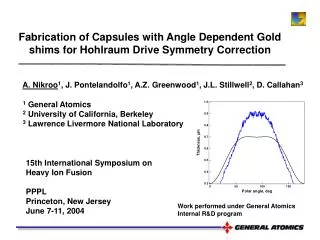
A. Nikroo1, J. Pontelandolfo1, A.Z. Greenwood1, J.L. Stillwell2, D. Callahan3 1 General Atomics 2 University of California, Berkeley 3 Lawrence Livermore National Laboratory Fabrication of Capsules with Angle Dependent Gold shims for Hohlraum Drive Symmetry Correction 15th International Symposium on Heavy Ion Fusion PPPL Princeton, New Jersey June 7-11, 2004 Work performed under General Atomics Internal R&D program
Innovation in target design and fabrication can be used to compensate for drive asymmetry • In the HIF hybrid target, most of the energy is deposited behind a shine shield • Radiation flows around the shield and results in a bright source around the shield • This causes a large P4 asymmetry • The P4 asymmetry can be corrected using a shim to remove excess radiation • Initial examination of this concept was done on a target shot in SNL’s double ended Z-pinch Z-axis Au shim Ge-CH equator XY Shims can be used to fix asymmetries in all indirect drive targets (heavy ion, laser, z-pinch)
Summary of angle dependent gold shim fabrication process • Ge-CH mandrels were made using well developed ICF capsule fabrication techniques • Gold shim coating was deposited by magnetron sputtering • Using masks patterned coatings were produced • Coatings on flats were used as initial guidelines • Gold thicknesses on shells were determined by x-ray transmission (contact radiography) • Profile similar to desired profile was produced • Adjustments to process is necessary to obtain desired profile
The decomposable mandrel technique was used to fabricate Ge-CH shells Heat Coat Decomposable Mandrel: Final Ge-CH shell Glow discharge Polymer coating Poly-a-methylstyrene (PAMS) (GDP) • Process allows fabrication of shells with: • Desired diameter (~ 5 mm) • Wall thickness (~ 20-30 µm) • Sphericity (>99.9%) • Wall thickness uniformity (<0.2 µm) • Dopant content (germanium- ~ 2 at.%) High aspect ratio- fragile
The desired gold shim profile was a combination of P2 and P4 Legendre polynomials Desired shim profile for this experiment was: • The relative contribution of P2 and P4 needed to be an adjustable parameter • Shim coating process had to be flexible enough to accommodate such changes: • Use of multiple masks • Adjustment of mask-shell distance XZ Projection vs. polar angle Designed to zero out P2, P4 double ended Z-pinch asymmetry
Gold coating was deposited using physical vapor deposition via magnetron sputtering Vacuum Chamber Au target -500 V Ar+ Impact Mask Spinning Pan xyz Micro-manipulator Ge-CH mandrel Motor • Sputtering provides an important processing knob • Background argon pressure determines mean free path of gold atoms • Affects scattering and deposition pattern of gold atoms • Masks were used to pattern gold coating Sputter system
Combination of coatings through two different masks could be used to obtain different profiles 7.5 10 1.085 5 Single 2.31 2.2 1.085 Double • Aluminum plate with precision milled slots was used as mask • Varying slot dimension varied coating profile • Single and double slot masks could be combined to fine tune pattern Combination mask Coatings on flat substrates
Gold coating pattern could also be changed by varying the mask-substrate distance Movable mask • For a given mask the separation between mask and substrate could be changed • Coatings spread with separation of mask from substrate • This allowed obtaining various profiles by adjusting mask-substrate distance 1mm 2mm Coatings on flats
The desired profile could be produced on flats very closely Actual Desired • Coatings using: • ~ 2mm mask-substrate distance • 0.8* single slot + 1.0 double slot • produced desired pattern on flats • Coatings on shells were likely to be deficient near the poles • This, however, was used as a starting point for producing the shim on shells • Coating rate on shells needed to be determined
Characterization of coatings on shells provided a difficult challenge • Interferometry or profilometry were not possible • X-ray transmission detected by contact radiography was readily available and used: • Convolution of x-ray source, coating, x-ray film signal was calibrated on flats • X-ray signals was linear for the range of interest • Uncoated shell signal was subtracted • Shell signal was corrected for cord length in ZX projection • Data near poles suffers from saturation due to large cord length
Coatings on flat substrates were used to calibrate x-ray transmission signal X-ray Interfer • Coatings through single and double slots on flats were measured by interferometry • Coatings were duplicated on thin CH film (~ zero substrate signal) • X-ray signals were recorded using various tube voltage and exposure times • The settings that led to highest x-ray vs. interferometry linearity were used for measuring shells • It also allowed thickness determination on shells Single mask coating 8 bit digitized line out
X-ray signal was linear in most of the range of interest ZX profile cord length of desired profile • X-ray signal measures projection of shells thickness on ZX plane • Cord length for desired profile is ~ 0.5-1.2 µm • X-ray signal is linear vs. thickness for this range • Proper exposure and source voltage settings are required! • Region of linearity could be changed by changing settings
Shells were precisely positioned under the masks • Shells were mounted on ~ 200 µm tungsten stalks • Stalk was attached to motor shaft with wobble of < ~ 50 µm • Interferometer was used to determine position of top of shell to < 1 µm • Measuring microscope was used for lateral position determination (~1 µm) • XYZ micrometer stage was used to move mask over shells to within ~ 2 µm Tungsten stalk Shell mounting for coating
X-ray signal from shells coated through single mask was used to determine coating thickness shell flat Uncoated shell ZX thickness projection Au coated shell • Single slot pattern on shell was very similar to that on flats • X-ray exposure settings were changed for these thinner coatings
shell flat X-ray signals from double slot mask indicated lower rate near equator Au coated shell • Coatings using double slot mask were thicker near equator and thinner at the poles than expected from flat data • Shell curvature and larger distance between poles and mask are responsible • Data analyzed after shells were delivered for shots • We will make adjustments for next series ZX thickness projection
A profile similar to the desired profile was produced on target shells actual desired • Final profile was not exactly as desired on shells delivered for shots • Coating near equator was thicker than desired- would it reverse P2 asymmetry? • Coating near poles was thinner • Adjustment of the double slot mask is needed • Shells were assembled and shot at SNL P2 symmetry was reversed in shot on SNL Z-pinch as expected
We hope to simulate process using Monte Carlo simulation to obtain better predictive capability • Direct Monte Carlo simulation program DS2V of G. Bird • Initially determine gold atom distribution near masks • Use that distribution to simulate coating under masks as function of distance on flat and spherical substrates
We have produced angle dependent gold shim targets • This innovative target can compensate for driver asymmetry • Targets were produced using ICF target fabrication infrastructure at General Atomics • Gold coating thickness could be patterned by coating shells through: • Various masks • Adjusting mask-substrate distance • The desired pattern was nearly produced • However, adjustments are needed to faithfully produce desired profile • Other characterization techniques also need to be examined in the future