Download
1 / 10
100 likes | 126 Vues
Here we go over how a load cell measures axial thrust, what axial thrust actually is, how axial thrust is built up in centrifugal pumps and much more.

E N D
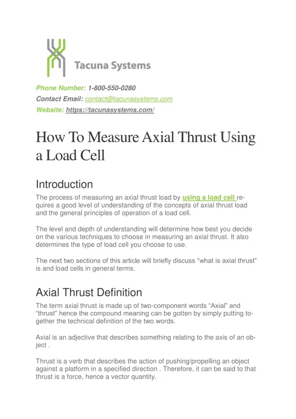
Phone Number: 1-800-550-0280 Contact Email: contact@tacunasystems.com Website: https://tacunasystems.com/ How To Measure Axial Thrust Using a Load Cell Introduction The process of measuring an axial thrust load by using a load cell re- quires a good level of understanding of the concepts of axial thrust load and the general principles of operation of a load cell. The level and depth of understanding will determine how best you decide on the various techniques to choose in measuring an axial thrust. It also determines the type of load cell you choose to use. The next two sections of this article will briefly discuss “what is axial thrust” is and load cells in general terms. Axial Thrust Definition The term axial thrust is made up of two-component words “Axial” and “thrust” hence the compound meaning can be gotten by simply putting to- gether the technical definition of the two words. Axial is an adjective that describes something relating to the axis of an ob- ject . Thrust is a verb that describes the action of pushing/propelling an object against a platform in a specified direction . Therefore, it can be said to that thrust is a force, hence a vector quantity.
Figure 1. An illustration of axial thrust The definitions of these two words show that axial thrust definition means a propelling force that is applied along the axis (also called axial direction) of an object in order to push the object against a platform in a particular direc- tion. This also means that the force acting can that of compression in a negative direction or a tension in a positive direction depending on the point of reference. What is axial thrust? It is the type of driving force that is generated in the propulsion system of an airplane, a pogo stick, and gears, steam turbines, stage pumps, double suction impeller. There is need for axial thrust balancing in centrifugal pump by the rotor. The next three section of this article briefly discusses how centrifugal pumps work, analyses how axial thrust loads/axial forces are produced in- side the pumps and procedures to follow in balancing axial thrust in pumps.
Centrifugal Pump A centrifugal pump is a machine that converts rotational kinetic energy (of a rotor) to hydrodynamic energy for the purpose of transporting fluids from one section to another. In other words, it is a machine that generates cen- trifugal forces that helps to push out the fluids entering it. The inlet side of the machine through which fluid particles enter the pump is called the suction side. The outlet side through which the fluid particles es- capes the machine is called the discharge side. The pressure at the dis- charge side is greater than the pressure at the suction side. Centrifugal pumps have two major components other than the driving unit (e.g. an electric motor). These are: The impeller: This is made of backward curved vanes or blades. The impeller is a rotating part of the centrifugal pump that is connected to the driving unit through a shaft. The impeller vanes rotate counter- clockwise to the motor’s rotor direction so as to be able to push out the fluid particles towards the outlet. There are different types of im- pellers which are the open impeller, semi-open impeller and shrouded impeller. The volute casing: This is a specially designed spiral casing whose area increases along the direction of fluid flow. This design, there- fore, helps to force fluid out the discharge side. The casing protects the pump and houses balancing holes. The balancing holes are points where balancing weights are fixed so as to ensure that the center of mass of the pump’s parts aligns with the center of mass of the driving unit’s rotor (motor’s rotor shaft). The other parts of the centrifugal pumps are: The shaft that connects the impeller to the driving unit.
The bearings located on the shaft that helps to maintain radial and axial thrust load clearance. A double suction impeller has bearings on both sides (front and back side). The sealing which prevents dirt from entering the parts of the pump and ensures protection against fluids. How Axial Thrust Is Built Up In Centrifugal Pumps In single stage pumps, as the device is powered on and the shaft begins to rotate, there are two sets of forces acting on the shaft. The first sets of forces are the radial forces created by the unbalanced pressure by the cas- ing design. The second sets of forces are the axial forces, part of which is caused by the pressure difference between the part of the shaft directly at- tached to the back side of the impeller and the front side of the impeller. As the fluid gets to the other side of the impeller, that is, the discharge side of the pump, parts of the liquid tend to push against the casing thereby try- ing to push out the shaft outwards along its axis through the driving unit. The pushback force acting along the shaft’s axis also contributes to the ax- ial thrust.
Figure 2. Axial force in a centrifugal pump Furthermore, as the shaft rotates and the impellers start to push out fluid, over time dirt particles are deposited on the blades, thereby causing an un- balance in the system. This, therefore, generates axial thrust components on the shaft and the motor. This effect is also common and more frequent in multistage pumps due to the difference in the pressure between the impellers which causes a misa- lignment in the total axial balance. Balancing Axial Thrust The process of balancing axial thrust is very important so that the pump can operate properly. Balancing the axial thrust requires the axial thrust to be offset. Some of these offset techniques include: The use of thrust bearings to support high axial loads especially in heavy-duty centrifugal pumps The use of a balance piston. The balance piston must be placed so that there is an opening beneath it that ensures the fluid flows back
towards the inlet. If this is not done, then the pressure exerted on it by the flow of the fluid will also increase the total axial thrust. Proper alignment and arrangement of the impellers This balancing will reduce stress and damages to the structure. It will re- duce the stress exerted on shaft bearings (wearing rings, loose rings, and thrust bearings). It will also prevent damages to the seal that protects the centrifugal pump. What Are Load Cells? Load cells are sensor devices. Sensors are used to detect a physical stimu- lus or phenomenon and then produce an output that is proportional to that stimulus. Load cells, in this case, are capable of detecting loads and forces, hence, they are useful for measuring axial thrust load. The load cell system generally is a linear system, however, it is of different types and designs, and hence some may vary in their input-output relation- ship. Load cells types include pneumatic load cells, hydraulic load cells, strain gauge load cell, capacitive load cell etc. the most commonly used type is the strain gauge load cell due to its several advantages. As said earlier, load cells are sensors, however, in modern control systems, especially, the one in this context (measurement of thrust), an electrical transducer is the most efficient sensor type to use. A transducer is a sensor that detects a physical stimulus and then produces an electrical output sig- nal that is proportional to it. Each load cell type can be designed in a way for its output to produce an electrical signal, however, the most convenient and cost-effective type to use is the strain gauge type which is a passive transducer. The figure be- low shows a simple strain gauge load cell.
Figure 3. A certified single ended beam strain gauge load cell How Load Cells Work Load cells have a general principle of operation. The load cell device is made to have a platform on which the load (force/weight) to be quantified is applied. The applied force is transmitted through a medium which acts to produce an output signal. Pneumatic and hydraulic load cells are catego- rized as force-balance devices. Strain gauge load cells offer the best set of features for measuring a thrust and its underlying mechanism relies on a device called a strain gauge. The strain gauge is the passive element of the device that generates an electri- cal output signal when a force is applied to the loading point of the load cell. There are various designs of a strain gauge load cell and also configu- rations of its strain gauges. Analysis of the Design Requirements of a Simple Axial Thrust Measuring System Processing all the concepts talked about in the earlier sections of this arti- cle, let us now take a look at the basic requirements for a simple axial thrust measuring system. 1.Determine The Maximum Force: It is essential to determine the lim- its of the force that the propeller or the engine will generate. This can be done by mathematical calculations based on the constants and
variables of the engine. It is necessary to do this as it will help in se- lecting a load cell with a rated output capacity equal to or greater than the expected maximum force. 2.Determine The Direction Of The Force: It should be noted that thrust is a reaction force and it will act opposite to the original force generated in an engine. Therefore, in practical terms, always cater to both compression and tensile forces. Select a load cell that can sup- port both directions of forces. 3.Select The Load Cell: Proceed to select the load cell that suits the basic requirements above. Always ensure to check the datasheet of the load cell for its specifications and also its certifications. Certifica- tions will help to ensure that the load cell device has been tested and approved for use, hence, it is safe to work with. The environmental compatibility of the load cell should also be considered. 4.Construction of a Thrust Stand/Frame: The load cell will always require a mounting kit and this can be purchased alongside the de- vice. A proper mounting kit contributes to obtaining an accurate re- sult. The mounting kit should then be arranged in a thrust frame. The construction of this frame should consider the following: A fixed support frame to which one end of the load cell will be mounted. An alignment system to ensure the thrust axis of the engine is properly applied to the load cell’s application point, this will prevent issues of off-axis loading. A simple alignment system might incor- porate optical devices like lasers. For centrifugal pumps alignments might be off times due to unbalancing, so the system might also be made flexible to cater for it 5.System Calibration: A simple calibration system for this purpose might utilize a screw jack driven by an electric motor to apply both compressive and tensile forces to the load cell through a series of levers and pull rods. Further processes should be carried out in order to tare the load cell and also the setting up of an automatic calibrator system
6.Mounting and Testing: The next step will be to mount the engine whose axial thrust is to be measured in the measuring system. Per- form all the necessary checks and proceed to power on the system. This should be carried out in a controlled environment under proper supervision and approval. Figure 4. A simple test thrust stand Figure 5. A vertical and horizontal thrust test stand
There are other procedures to carry out, part of which majorly involves pro- cessing the output of the load cell to ensure an accurate result. The output of the electrical transducer should be conditioned. Conditioning involves filtering against background noise, amplification of the filtered signal and conversion from analog form to a digital signal. The digital signal can then be further processed by a microcontroller to display the thrust force and the unit of measurement. SOURCES Essential guide to load cells Centrifugal Pumps by Dan Campbell, Noah Brown, John Cox Centrifugal Pumps by Christian Allerstorfer Phone Number: 1-800-550-0280 Contact Email: contact@tacunasystems.com Website: https://tacunasystems.com/