Download
1 / 45
720 likes | 1.23k Vues
CPCCBC 4012A Read and interpret plans and specifications. 18740 Certificate IV Building & Construction (Building). Glenn P. Costin. Introduction. Purpose To develop the necessary skill and knowledge to read and interpret construction plans and associated specifications and schedules.

E N D
CPCCBC 4012ARead and interpret plans and specifications 18740 Certificate IV Building & Construction (Building) Glenn P. Costin
Introduction Purpose • To develop the necessary skill and knowledge to read and interpret construction plans and associated specifications and schedules. Architectural drafting is a language like any other: One must be fluent to understand its various nuances and peculiarities. Likewise, as a language it changes over time, so one must remain engaged. Glenn P. Costin
Standards and Codes Building Code of Australia (BCA) Calls for various Australian Standards: AS 1100.101 – 1992 (and amendments) Technical Drawing – General Principles AS 1100.301 – 1985 (and supplements) Architectural Drawing HB 47 – 1993 Dimensioning and Tolerances Glenn P. Costin
1. Types of Drawings Sketches Critical part of the initial design phase Glenn P. Costin
Initial Sketches Glenn P. Costin
Sketch Plans or ‘Roughs’ Good design evolves from the doing, yet is reflective of being “We shape our buildings; thereafter they shape us”. Winston Churchill Glenn P. Costin
Pictorial Drawings • Orthographic Vs Pictorial What we draw ‘orthographically’ What we ‘see’ Glenn P. Costin
30o Pictorial Types Isometric Shows 3 dimensions. All dimensions full length. Glenn P. Costin
45o Oblique Pictorial Types Shows 3 dimensions. Receding dimensions reduced (1/2 size). Glenn P. Costin
Drawing Plane Vanishing Point (VP) Vanishing Point (VP) Horizon Line Perspective Orthographic Ground Line Spectator Position (SP) Two Point Perspective Pictorial Types Perspective Glenn P. Costin
Pictorial Types Presentation Drawings Wright Frank Lloyd : Falling Water Mill
Construction Drawings The ‘Plans’ • Orthographic • Drawn to Scale • Offer multiple views and details • Provide evidence of compliance • Submitted to relevant authorities • Show location of construction • Used for quoting and tendering • Allow off site manufacturing • Legal documents (in disputes) • Are the ‘construction manual’ Glenn P. Costin
Aspects of construction Plans Site and Location Plans • Small Scale (1:1000) • Location Plans show where the building site is Glenn P. Costin
Aspects of construction Plans Site Plans • Make clear the location of the structure on the site • Show the lay of the land • Show Boundary lines • Building Orientation • Show Existing Structures, easements and the like. • Scale 1:200 - 1:500
Aspects of construction Plans Floor Plan • Arial view • Details horizontal dimensions • Location of rooms • Position of fixtures • Roof outline • Thickness of walls • Scale 1:100 Glenn P. Costin
South Elevation East Elevation Aspects of construction Plans Elevations • Side views of structure • Heights or ‘elevations’ • Not a lot of measured detail • Only height measurements offered • Scale 1:100 Glenn P. Costin
Aspects of construction Plans Sections • Cut vertically through building • Location of cut a perspective shown on floor plan • Show inside of building • Show detail hidden from elevations • Often heavily annotated • Scale 1:100 or larger Section A-A Glenn P. Costin
Aspects of construction Plans Bracing Plan • Recent addition • Show type and location of bracing • Accompanied by bracing schedule Glenn P. Costin
Aspects of construction Plans Overlays • Simplified Floor Plan • Required for extensions and renovations • Identify new work from old Glenn P. Costin
Aspects of construction Plans Details • Enlargements of key areas • Offer clearer picture of how something is to go together • Show work that may differ from standard building practice • Often heavily annotated Glenn P. Costin
Aspects of construction Plans Schedules • May be stand alone or be accompanied by other drawings • Door & Window • Materials & Finishes • Bracing Glenn P. Costin
Aspects of construction Plans • Service Details • Plumbing • Heating • Air conditioning • Electrical • Vary in scale and complexity depending upon requirements Glenn P. Costin
Aspects of construction Plans Amendment Drawings • Document revisions • May affect one or all drawings • Identified by revision block or number • Triangle points to revision Glenn P. Costin
2. Symbols and Abbreviations Symbols: An agreed array of objects, characters or figures Three main types of symbols used • Drawing (material renderings, doors etc.) • Fixture (sink, basin, stove, dishwasher) • Services (electrical, heating, cooling) Glenn P. Costin
Symbols and Abbreviations Be aware that some symbols are nation specific. E.g.: • Australia • door hinged on the right hand side. • window hinged at top (Awning sash) • United Kingdom (Australia till late 1960s) • door hinged on the left hand side • window hinged at bottom (hopper sash). Glenn P. Costin
Continuous Dashed Centre Symbols and Abbreviations Common Line Types Glenn P. Costin
Symbols and Abbreviations Line Types Glenn P. Costin
Symbols and Abbreviations Abbreviations and Terms • WRC Western Red Cedar • KDHWD Kiln Dried Hard Wood • GAL Galvanised • GL Ground Line • USCL Underside Ceiling Line • FFL Finished Floor Line Glenn P. Costin
3. Key Features on Site Plan • Location & Orientation • Datum • Access & Egress • Contours • Slopes • Geographical & Topographical Glenn P. Costin
Location & Orientation Hidden Lane Glenn P. Costin
Important Terms Permanent Bench Mark (PM or PBM) Often located in pavements Temporary Bench Mark (TBM) Usually positioned by a licensed surveyor Datum In this case Sea Level Station Benchmarks: Permanent (PM) or Temporary (TBM) marks of known height above the original datum (sometimes used as the datum with a nominated height). Datum: The point to which all other heights are referenced (may be sea level or a height nominated arbitrarily). Station: The location of the levelling instrument (may be more than one ‘Station’ in a survey). Glenn P. Costin
Peg C records a Fall when sighted after Peg B Peg B records a rise when sighted after Peg A Fall: The decrease in height between a location (Datum, peg, or mark) and the one previous to it Fall: The decrease in height between a location (Datum, peg, or mark) and the one previous to it Important Terms Rise: The increase in height between a location (Datum, peg, or mark) and the one previous to it. B C A Glenn P. Costin
Sea Level or ‘Datum’ R.L. 0.000 This means the ground at Peg A is 75.250m above sea level Important Terms Reduced Level (R.L.): The height of a location (datum, peg, or mark) relative to the nominated reference point (sea level, bench mark of given height, or the like). Foresight 1.000 Ground rises 0.200m Backsight 1.200 Peg B R.L. 75.450 Peg A R.L. 75.250 From Previous survey. The word ‘reduced’ is used in this case to mean ‘taken from’. Every R.L. is ‘taken from’ (reduced), and so has a relationship to, something else. Glenn P. Costin
Contour Lines 180 170 160 150 150 160 170 180 Glenn P. Costin
Easements • Land that someone other than the ‘owner’ has legal right to access • May limit or inhibit building • Will always be on title documents • Must be shown on site plan • Examples include sewer lines and other underground services, water courses, public rights of passage and the like. Glenn P. Costin
4. Key Features on Drawings Task: Using the plan set provided complete the table in the notes. Glenn P. Costin
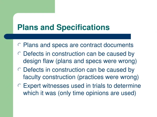
5. Specifications • Form part of contract documents • Have legal standing Specify: Materials Works to be undertaken Quality of work Obligations (Builder, Owner, Contractors) Standards and Codes to be adhered to Statutory requirements Glenn P. Costin
Specifications • Standard Specifications available (MBA, HIA, Natspec) • Builders/Architects/Designers may write their own • Not all domestic construction will have a specifications ‘book’ • May include Provisional Sum (PS) and Prime Cost (PC) Items Glenn P. Costin
Provisional Sum Items Some work cannot be accurately quoted due to unknowns within the scope of that work E.g.: Rock Excavation, Landscaping, Retaining walls • May be higher or lower than the PS amount • To provide a quote for the full job an estimate amount is entered that ‘provides’ for the work. • Once work is completed the actual cost is documented and the client billed accordingly • This amount in original quote. • Builders should clearly identify PS items for themselves and to their clients Glenn P. Costin
Prime Cost Items • Applies to items and or materials which might not be chosen by the client until work has progressed. • Actual cost of items accounted in final statements to client. Prime Cost (PC) items might include: • Tiles • Sinks • Taps • Lights etc. Glenn P. Costin
Variations to Standard Specifications Clients can call for variations to the standard specification Variations can be to: • quality expected • Listed PC items • Materials and finishes Variations must be recorded (Addendum to Specifications or noted as variation to plans) Glenn P. Costin
Essential elements of Specifications Specifications broken into sections such as: • Introductory Section • Statutory Requirements • Owners Obligations • Plans, Permits, Fees • Site Works • Footings And many other sections covering specific trades such as Carpentry, Joinery, Roofing, Bricklaying and the like. Glenn P. Costin
Essential elements of Specifications • Many elements of construction are held within the Specifications only • Builders need to identify and interpret these elements for quoting and construction purposes • Builder needs to ensure client is aware of these elements. • Builder needs to ensure supervision on and off site covers these elements Glenn P. Costin
6. Non-Structural Aspects of Specifications Aspects that cover elements of structure that do not carry load or resist force (uplift, wind forces, earth pressures etc.) E.g.: Plumbing and electrical, fittings, appliances etc. • Client generally has input into selection of some non- structural items, or elements of items (brick colour, face etc.) • Builder may be called upon for advice • Builder should be aware of limitations to choice described by the Specifications (e.g. wind load capacity of glazing) Glenn P. Costin