Download
1 / 47
500 likes | 714 Vues
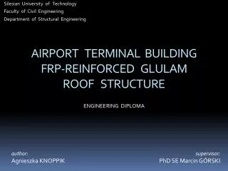
AIRPORT TERMINAL BUILDING FRP-REINFORCED GLULAM ROOF STRUCTURE. Silesian University of Technology Faculty of Civil Engineering Department of Structural Engineering. ENGINEERING DIPLOMA. author: Agnieszka KNOPPIK. supervisor: PhD SE Marcin GÓRSKI. Aim of project.

E N D
AIRPORT TERMINAL BUILDINGFRP-REINFORCED GLULAMROOF STRUCTURE Silesian University of Technology Faculty of Civil Engineering Department of Structural Engineering ENGINEERING DIPLOMA author: Agnieszka KNOPPIK supervisor: PhD SE Marcin GÓRSKI
Aim of project The aim of project was to design a roof structure of passenger terminal building for Katowice International Airport made of FRP-reinforced glue-laminated timber frame system taking into consideration operation of the building under standard operation conditions.
Range of project 1. Architectural concept of terminal building 2. Design models of roof structure • beam model (simplified) • surface model (detailed) 3. Composition of loads and combinations of loads under standard operation conditions 4. Stength & stability analysis of roof structure • analytic method (simplified) • finate element method (detailed) 5. Spatial stiffening of roof structure 6. Constructional drawings of main structure and structural elements
1. Project basis Requirements 1. Legal requirements aviation law building law 2. Technical requirements complex development of apron and terminal 3. Architectural requirements functional program
2. Review of existing structures Passenger terminals • Terminal 3 at Beijing Capital International Airport, China • 986,000 m2 of total floor area • 3.5 km long • 5 floors • 50 mln passengers/year • structure – standard steel modules • Teminal at Chek Lap Kok Airport, Hong Kong • 515,000m2 of total floor area • 1.2km long • structure – RC frames, steel vaulted frames, waffle floor • New Teminal 2 a Mexico City International Airport, Mexico • 350,000 m2 of total floor area • RC with masonry filling
2. Review of existing structures Glulam hall structures arches truss solid domes ribbed net frames column - beam curved
3. Structural solutions Architecture ground floor first floor My architectural concept
3. Structural solutions Structure B x L = 42.9 x 174.9 m; H ≈ 20 m Load-bearing structure FRP-reinforced glulam cable-stayed frames every 6 / 9 m.
4. Loads Static model – beam model arch elements replaced with sequence 0f straight segments flexible supports replacing cables Rough assesment of internal forces distribution.
4. Loads Dead load case A - max. dead load self load of roof covering self load of structure installations roof bracing case B - min. dead load
4. Loads Wind load PN-77-B-02011 • qk = 550 Pa (account for thrust) • Ce = 1.2 (height-dependent) • β = 1.8 (initial assumption)
4. Loads Wind load case D wind from the right case C wind from the left Case E wind from the front
4. Loads Snow load EN 1991-1-3 • sk = 0.9 kN/m (zone II) • Ce = 0.8 (windswept topography) • Ct = 0.77 (glass roof covering)
4. Loads Snow load case F balanced situation case G unbalanced situation 1 case H unbalanced situation 2
4. Loads Temperature EN 1991-1-5 • difference between FRP and glulam: thermal expansion coefficients heat transfer • changing cross-sections :different uniform temperature • moisture Temperature difference case I - summer ΔT = 200C case J - winter ΔT = -200C
5. Combinations of loads Combinations of loads Fundamental combination (ULS) Characteristic combination (SLS) • alwaysA / B + optionallyC / D / E + F / G/H + I / J dead load wind load snow load temperature
5. Combinations of loads Envelopes of internal forces Bending moments Shear forces Normal forces
FRP –reinforced glulam Moment curvature model – similar to reinforced concrete 6. FRP-reinforced glulam • linear-elastic-ideal-plastic relationship within cross-section • linear-elastic behaviour of FRP • Bernoulli hypothesis applied • shear strength of bond between FRP and timber greater than shear strength of timber along fibres • ideally stiff bond, so εw = εf • substitute section method for stiffness evaluation • influence of glue on stiffness neglected, Eglue = Etimber
7. ULS analytic Mechanism of action. Modes of failure
Ultimate Limit States 7. ULS analytic • bending with axial tension • bending with axial compression (horizontal elements) • bending with axial compression (vertical elements)
7. ULS analytic Ultimate Limit States strength condition at bent segments shear strength effective geometrical data ecountered
Ultimate moment 7. ULS analytic • effective height: h = h0a c e h = h0 – hpb d f • neutral axis location: hn = hn(hf, E0, Ef, hp) a b hn = hn(hf, E0, Ef, hp, fm, fc) c d hn = hn(hf, E0, Ef, hp, fm, fc, εc) e f • modification factor: kM = kM(hn, hf, E0, Ef) a b kM = kM(hn, hf, hc, E0, Ef) c d e f
7. ULS analytic ULS control Control sections: bending + compression Control sections: shear
Static model – surface model 8. ULS FEM
Static model – surface model 8. ULS FEM
Dynamic wind action. Modal analysis 8. ULS FEM assumption β = 1.8 satisfactory! n = 0.45 β = 1.51 n = 1.28 β = 1.41 n = 1.34 β = 1.41 n = 1.90 β = 1.41 n = 2.94 β = 1.42 n = 4.07 β = 1.41
Ultimate stress 8. ULS FEM Model 1: High concetration of stresses at the internal support Model 2. Increased stiffness of cables. Little change in stress distribution Model 3. No cables. Little change in stress distribution Model 4. Second column introduced. Satisfactory stress distribution
Ultimate stress 8. ULS FEM • Reinforcement applied: • support area - 3 FRP strips h = 1.8mm, Ef = 300GPa along top fibres • sag area – 1 FRP strip h = 1.4mm, Ef = 300GPa along bottom fibres 3 strips σt > 90% ft,0,g,d 2 strips σt > 80% ft,0,g,d 1 strip σt > 70% ft,0,g,d Model 5. Scheme
9. SLS Serviceability Limit States instanteneous deflection final deflection stiffness increase kEI ∙ EI kEI = kEI(hf, hp) negligible effects of FRP creep ufin = uinst (1 + kdef) ufin ≤ ufin,net
9. SLS Serviceability Limit States Deformation of girder under characteristic combination of loads Horizontal displacements Vertical displacements
9. SLS Serviceability Limit States Control sections section I-I uins = 4.1cm kEI = 1.0 ufin = 6.2cm > unet = 5.0cm section II-II uins = 12.0cm kEI = 1.1 ufin = 16.0cm > unet = 10.0cm
9. SLS Serviceability Limit States Horizontal displacements Vertical displacements + reinforcement in sag area (3 FRP strips h = 1.8mm, Ef = 300GPa)
9. SLS Serviceability Limit States Control sections section I-I uins = 3.1cm kEI = 1.0 ufin = 4.6cm < unet = 5.0cm most unfavourable case A+H 1 strip kEI = 1.10 u1s = 6.2cm 2 strips kEI = 1.19 u2s = 6.7cm 3 strips kEI = 1.26 u3s = 7.1cm section II-II uins = 8.4cm kEI = 1.25 ufin = 9.9cm < unet = 10.0cm
10. Spatial stiffening Bracings wind truss bracing • located horizontally between adjacent frames • transfer wind load to foundations • located horizontally between adjacent frames • protect nodes of compressed elements against transverse movement
10. Spatial stiffening Wind truss transverse wind truss every 30m longitudinal wind truss along outer edge of roof wall truss
10. Spatial stiffening Roof wind trusses Transverse truss designed for uniformly distributed load q Longitudinal truss designed for slenderness conditions: compressed elements λ ≤ 250 tensiled elements λ ≤ 350
10. Spatial stiffening Wall trusses Wall truss being a component of transverse roof truss designed for internal forces under q load Wall truss between external columns designed for reaction from girder on columns R = 23kN
10. Spatial stiffening Vertical bracing
10. Spatial stiffening Vertical bracing Designed for concentrated load Q Q = q ∙ a
10. Spatial stiffening Bolted joints (steel-to-timber joint) Thickness of steel plate Required number of screws in joint per element t = t(d, fuk) R = R(fh,1,d, t1, d, Myd) Number of connectors influences minimum width of connected element!
Supports Support of girder on RC deck – pivot support Support of girder on RC deck – column support Reaction from girder V clamp stength of rocker/hull and roller Reaction from girder V clamp stength of steel bearing and column 10. Spatial stiffening
Glued joints 10. Spatial stiffening shear stress tensile stress across fibres
CONCLUSIONS The effect of reinforcement on strength and stiffness of glued-laminated timber elements Comparison of analytic method and final element method
Articles Books Bibliography 9 Polish works 21 foreign works Ajdukiewicz A., Mames J.: Konstrukcje z betonu sprężonego. Polski Cement Sp. z o.o., Kraków (2004) Flaga A.: Inżynieria wiatrowa. Podstawy i zastosowania. Wydawnictwo “Arkady”, Warszawa (2008) Jasieńko J.: Połączenia klejowe i inżynierskie w naprawie, konserwacji i wzmacnianiu zabytkowych kontrukcji drewnianych. Dolnośląskie Wydawnictwo Edukacyjne, Wrocław (2003) Łubiński M., Filipowicz A., Żółtowski W.: Konstrukcje metalowe. Część I: Podstawy projektowania, wydanie 2zm. Wydawnictwo ``Arkady'', Warszawa (2000) Masłowski E., Spiżewska D.: Wzmacnianie konstrukcji budowlanych. Wydawnictwo ``Arkady'', Warszawa (2000) Michniewicz Z.: Konstrucke drewniane. Wydawnictwo “Arkady”, Warszawa (1958) Mielczarek Z.: Nowoczesne konstrukcje w budownictwie ogólnym. Wydawnictwo “Arkady”, Warszawa (2001) Neufert E., Neufert P.: Architect’s data. 3rd edition Nożyński W.: Przykłady obliczeń konstrukcji budowlanych z drewna. Wydanie 2 zm., Wydawnictwa Szkolne i Pedagogiczne S.A., Warszawa (1994) Świątecki A., Nita P., Świątecki P.: Lotniska. Wydawnictwo Instytutu Wojsk Lotniczych, Warszawa (1999)
Standards Bibliography PN-77-B-02011 – Obciążenia w obliczeniach statycznych. Obciążenie wiatrem. PN-81/B-03020. Grunty budowlane. Posadowienie bezpośrednie budowli – Obliczenia statyczne i projektowanie. PN-82/B-02402. Ogrzewnictwo – Temperatury ogrzewanych pomieszczeń w budynkach. PN-90-B-03200. Konstrukcje stalowe. Obliczenia statyczne i projektowanie. PN-B-03150:2000. Konstrukcje drewniane – obliczenia statyczne i projektowanie. PN-B-03264:2002. Konstrukcje betonowe, żelbetowe i sprężone – obliczenia statyczne i projektowanie. prEN 1990 – Eurocode 0: Basis of structural design. prEN 1991-1-1 – Eurocode 1: Actions on structures - Part 1-1: General actions -Densities, self-weight, imposed loads for buildings. prEN 1991-1-3 – Eurocode 1: Actions on structures - Part 1-3: General actions – Snow loads. prEN 1991-1-5 – Eurocode 1: Actions on structures - Part 1-5: General actions – Thermal actions.
Legal papers Bibliography Web pages Convention on International Civil Aviation. 9th edition (2006) Konwencja o miedzynaroodowym lotnictwie cywilnym (2002) Prawo budowlane. Ustawa z dnia 7 lipca 1994 r. Prawo lotnicze. Ustawa z dnia 3 lipca 2002 r. Rozporzadzenie Ministra Infrastruktury z dnia 31 sierpnia 1998 r. w sprawie przepisów techniczno-budowlanych dla lotnisk cywilnych. Rozporzadzenie Ministra Infrastruktury z dnia 12 kwietnia 2002 r. w sprawie warunków technicznych, jakim powinny odpowiadac budynki i ich usytuowanie. Rozporzadzenie Ministra Infrastruktury z dnia 25 czerwca 2003 r. w sprawie warunków, jakie powinny spełniac obiekty budowlane oraz naturalne w otoczeniu lotniska. Rozporzadzenie Ministra Infrastruktury z dnia 30 kwietnia 2004 r. w sprawie klasyfikacji lotnisk i rejestru lotnisk cywilnych.
The End Thank you for attention