Download
1 / 30
300 likes | 404 Vues
Engineering 45. Electrical Properties-2. Bruce Mayer, PE Licensed Electrical & Mechanical Engineer BMayer@ChabotCollege.edu. Learning Goals – Electrical Props. How Are Electrical Conductance And Resistance Characterized

E N D
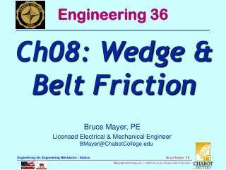
Engineering 45 ElectricalProperties-2 Bruce Mayer, PE Licensed Electrical & Mechanical EngineerBMayer@ChabotCollege.edu
Learning Goals – Electrical Props • How Are Electrical Conductance And Resistance Characterized • What Are The Physical Phenomena That Distinguish Conductors, Semiconductors, and Insulators? • For Metals, How Is Conductivity Affected By Imperfections, Temp, And Deformation? • For Semiconductors, How is Conductivity Affected By Impurities (Doping) And Temp?
Materials of Valence 4 (Grp IVA in the Periodic Table) Exhibit the property of Semiconductivity Si, Ge in Particular C, Sn to a Lesser Extent Also Observed in Compounds SemiConductivity • III-V → GaAs • II-VI → InP • Semiconductivity Characterized by • Insulative Behavior at Room Temperature • 106-1012 times LESS conductive than metals • INCREASING Conductivity with Increasing Temp • Opposite of Metal Behavior
Carriers in Semiconductors Conduction band (at T = 0 K unpopulated with electrons) Energy gap, Eg Valence band (at T = 0 K totally filled with electrons) • At non-zero temperatures, electrons are thermally excited from the valence band to the conduction band. • The activated “free electrons” and the remaining “holes” left behind act as two “ideal gases”!! • Certain types of impurities that are grown or implanted into the SemiConductor crystal produce extra free electrons or holes.
σ Data for Pure Silicon Note σ↑ as T↑ Si electrical conductivity, σ 4 10 3 10 2 10 1 10 (S/m) 0 10 pure (undoped) -1 10 -2 10 1 000 10 0 50 T(K) Intrinsic (Pure) Semiconductors • Why This Temp Behavior? • Semiconductor e− Band Structure • Thermal Energy Can Allow the e- to jump the “Forbidden” Gap between the “Valence” Band and the “Conduction” Band
Recall Conductivity Eqn from the Metals Dicussion Intrinsic (Pure) Carrier Concen • Note the Exponential Increase in the Intrinsic carrier Concentration, ni or • Since µ Does Not change nearly as much as ni with T
Conduction by e− & h+ Migration • Concept of Electrons (e-) & Holes (h+) • When e- moves to the Conduction Band it leaves Its Parent Atom Core, and Moves Freely • This Leaves behind an electron “HOLE” Which Results in a POSITIVELY Charged Atom/Ion Core • This Positive Charge can Attract an e- from an ADJACENT Atom, Thus the hole, h+, can move Left↔Right or Up↔Down • This Transfers the POSITIVE Charge-Center to the Adjacent Atom-Core • From an electrical current perspective, the Step-by-Step movement of the hole appears as the movement of a POSITIVELY Charged Particle; some Analogies • A bubble in a Liquid moves to the high side of a sealed tube • One open Spot in A parking Lots Moves Further from the Bldg as the cars move into the Close spot in Step-By-Step Fashion
valence electron hole electron hole Si atom electron pair creation pair migration - + - + no applied applied applied - + - + electric field electric field electric field e−& h+ Electrical Conduction • Schematically • In Metals, only e−Participate in Electrical Conduction (e−“sea”), But in Semiconductors HOLES also aid conduction
With the Participation of Electrons and Holes SemiConductor Conductivity • µe electron mobility, m2/V-s • µh hole mobility, m2/V-s • Where • q electronic charge, 1.6x10⁻¹⁹ Coulomb per e- or h+ • n electron concentration, e-/m3 • p hole concentration, h+/m3 • µe (4-30) times Greater Than µh • Why? • Parking Garage Analogy
n-Type Semiconductor illustrated in (a) & (c) p-Type Semiconductor illustrated in (b) & (d) Thus µe >µh h+ & e-Parking Garage Analogy
Phosphorus atom Boron atom hole 4 + 4 + 4 + 4 + 4 + 4 + 4 + 4 + conduction electron 4 + 5+ 4 + 4 + 4 + 3 + 4 + 4 + valence 4 + 4 + 4 + 4 + 4 + 4 + 4 + 4 + electron no applied no applied Si atom electric field electric field INtrinsic vs. EXtrinsic Conduction • INtrinsicSemiConductors → n = p • Case for “pure” Semiconductors; e.g., Si • EXtrinsicSemiConductors → n p • occurs when impurities are added with a different no. of valence e−’s than the host (e.g., Si atoms) • N-type EXtrinsic: (n>>p) • P-type EXtrinsic: (p>>n)
increases w/ Doping 4 10 0.0052at%B 3 10 doped 2 10 0.0013at%B 1 10 (S/m) electrical conductivity, σ 0 10 pure (undoped) -1 10 -2 10 1 000 10 0 50 T(K) Doped SemiConductors: vs T • N-Type Si, n vs T nd = 1021/m3 • FreezeOut → Not Sufficient Thermal Energy to ionize either Dopants or Si • Extrinsic → n = doping • Instrinsic → ni > doping • Reason: imperfection sites lower the activation energy needed to produce mobile e- or h+
Recall Reln for ni FreezeOut etc. nd = 1015/cc • The similar Reln for (N-Type) dopant Concentrations • FreezeOut → kT << [Eg or Ed] • Neither Si or Dopants are Ionized • Extrinsic → Ed < kT < Eg • Only Dopants are (Singly) ionized and nd >> ni • Intrinsic kT>> [Ed or Eg] • nd fixed at dopant at%, ni continues to Rise Si Dopant Ionization (eV)
P and N Type Semi Matls Brought Together to form a METALLURICAL (seamless) Junction The HUGE MisMatch in Carrier Concentrations Results in e- & h+ DIFFUSION Remember that? p-n Junction Physics • Carrier Diffusion • e- Diffuse in to the P-Type Material • h+ Diffuse in to the N-Type Material
In a p-n Jcn Carrier Cross-Diffusion is SELF-LIMITING The e-/h+ Diffusion leaves Behind IONIZED Atom Cores of the OPPOSITE Charge The Ion Cores set up an ELECTRIC FIELD that COUNTERS the Diffusion Gradient p-n Junction Physics cont. E-Field • For Si the Field-Filled Depletion Region • E-Field 1 MV/m • Depl Reg Width, xd = 1-10 µm • E-fld•dx 0.6-0.7 V • “built-in” Potential
A Rectifier is a “Check Valve” for Current flow Current Allowed in ONE Direction but NOT the other Side Issue → “Bias” Voltage A “Bias” Voltage is just Another name for EXTERNALLY APPLIED Voltage p-n Junction Rectifier E-Field
p-n junction Rectification A small “Forward Bias” Voltage results in Large currents Any level of “Reverse” Bias results in almost NO current flow Class Q: For Fwd Bias, Which End is +; P or N??? p-n Junction Rectifier cont E-Field • A: the P end • The Applied Voltage REDUCES the internal E-Field; This “Biases” The Junction in Favor of DIFFUSION
p-n junction No Applied Voltage p-n Junction Rectifier cont.2 • Internal Field ENHANCED • Carriers Pulled AWAY from Jcn; xd grows • Forward Bias Xd • Diffusion & E-Field in Balance, No Current Flows • Reverse Biased • Internal Field REDUCED • Carriers PUSHED and Diffuse to the Jcn where they are “injected” into the other side; xd Contracts
Properties of Rectifying Junction Reverse Forward • IN914 PN Diode • IF = 75 000 µA • IR = 0.025-50 µA
Transistors are “Transfer Resistors” Xsistors Have Three Connections Input Output CONTROL In Electronic Applications Transistors have TWO Basic Fcns Transistors • Amplification – Both Current & Voltage • On/Off Switching • Two Main Types • BiPolar Junction Transistor (BJT) • Good Amps • Field Effect Transistor (FET) • Depletion Mode • Good Amps • Enhancement Mode • Good Switches
The Classic pnp or npn configurations Basically Two pn jcns Back-to-Back c b e c b e BJT • npn In “Forward-Active” mode • b-e pn jcn FORWARD Biased • b-c pn jcn REVERSE Biased • Very Little “base” Current • Large emitter & collector currents • Good Current-Driving Amplifier
JFETs are “Normally On” Transistors Depletion Mode - JFET • Reverse Bias on the “gate” expands the NonConducting depletion region Until the channel is “Pinched Off” and no longer conducts • Gate is Reverse Biased → little Control-Current • Good Depl Region modulation → good I/V amp • OPEN “Channel” Between the “source” and “drain”
Insulated Gate Field Effect Transistors are Normally-Off devices Enhancement Mode - IGFET • Applying a Positive Voltage to the Gate will attract e−to the Channel • This will eventually “invert” a thin region below the gate to N-type, creating a conducting channel between S & D • IGFETs are Great Switches • Used in almost all digital IC’s • Back-to-Back pn Jcns Between “source” & “drain”
In Metals and Semiconductors, the atomic Ion-cores are fixed in the crystal Lattice Although they have the same charge as a “hole” they have almost NO “Mobility” Thus They do NOT contribute to Electrical Conduction Ionic Materials • Some Small Atomic Radii impurities can be CHARGED (ionic) and MOBILE within another material • e.g., Na+ can move fairly easily thru GLASS (SiO2) • The Total σ for Ionic Materials
As in the Electronic case Ionic Mobility • Diffusion • E-Field • Combine These two effects into Mobility • Where • NI Ion Concen, Ions/m3 • q electronic Charge • µI Ionic Mobility, m2/V-s • Two Forces move The Ions • Where • nI Ion Valence • DI Ion Mass Diffusion Coeff, m2/s • q, k, T as Before • Exercise → Find units for nI
Energy empty ConductionBand band GAP filled Valence band filled states filled band Ceramics • Most Ceramics have WIDE BandGaps • SiO2 9 eV • Si3N4 4.7eV • Thus Ceramics Tend to be VeryGood Electrical INSULATORS • But as with SemiConductors. for Ceramics nintrinsic Increases with Temperature • Thus Insulative Capacity DEGRADES at Hi-T • e.g; mullite = 3Al2O3•2SiO2 • ρ(25°C) 1012Ω-m; ρ(500°C) 106Ω-m
Polymers • Most “Standard” Plastics are Good Insulators • c.f. Their use as insulation on metal WIRES • Conduction Mechanism Not well understood • Believed to be More Electronic than Ionic • A Few Polymers are Good Conductors, with σ 107 S/m • About 2X HIGHER than Cu for Conductivity/lb • Mechanism appears to be SemiConductor-like with a doping Requirement • Discovery of these “synthetic metals” Resulted in the 2000 Chemistry Nobel Prize for Heeger, MacDiarmid and Shirakawa http://webpages.charter.net/dmarin/coat/#history
PiezoElectric Materials • Piezoelectricity application of force pressure produces Electrical Potential at rest compression induces voltage applied voltage induces expansion
WhiteBoard Work • Problem 18.30 • Antimony DopedGermanium • EXtrinsic form • All Sb Ionized • The μ’s: • μe = 0.1 m2/V·s • μh = 0.05 m2/V·s