Cardinality and Modality (ERD)
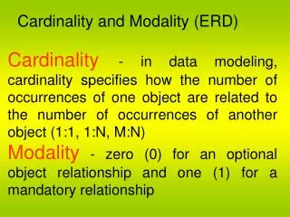
Cardinality and Modality (ERD). Cardinality - in data modeling, cardinality specifies how the number of occurrences of one object are related to the number of occurrences of another object (1:1, 1:N, M:N)


Cardinality and Modality (ERD)
E N D
Presentation Transcript
Cardinality and Modality (ERD) Cardinality- in data modeling, cardinality specifies how the number of occurrences of one object are related to the number of occurrences of another object (1:1, 1:N, M:N) Modality - zero (0) for an optional object relationship and one (1) for a mandatory relationship
Is provided with COUSTER REPAIR ACTION Cardinality: Implies that a single customer repair action (s) Cardinality: Implies that here may be repair action (s) Modality: Mandatory Implies that in order to have a repair action (s), we must have a customer Modality: Operational Implies that here may be a situation in which a repair action is not nessary
Functional Modeling and Information Flow (DFD) • Shows the relationships of external entities, process or transforms, data items, and data stores • DFD's cannot show procedural detail (e.g. conditionals or loops) only the flow of data through the software
External entity External entity Input data Intermediate data Output data Intermediate data Transform#3 Intermediate data Transform#1 Transform#4 Transform#2 Data store input Data store output Output data Data store External entity Input data External entity
Functional Modeling and Information Flow (DFD) (continue) • Refinement from one DFD level to the next should follow approximately a 1:5 ratio (this ratio will reduce as the refinement proceeds) • To model real-time systems, structured analysis notation must be available for time continuous data and event processing (e.g. Ward and Mellor or Hately and Pirbhai)
Monitored temperature Input “Continuous” Output “Continuous” Monitor and adjust temperature level Temperature set point
Behavioral Modeling (STD) • State transition diagrams represent the system states and events that trigger state transitions • STD's indicate actions (e.g. process activation) taken as a consequence of a particular event • A state is any observable mode of behavior • Hatley and Pirbhai control flow diagrams (CFD) can also be used for behavioral modeling
Creating Entity Relationship Diagrams The following steps are required to build an ERD. • Customer asked to list "things" that application addresses, these things evolve into input objects, output objects, and external entities • Analyst and customer define connections between the objects • One or more object-relationship pairs is created for each connection • The cardinality and modality are determined for an object-relationship pair • Attributes of each entity are defined • The entity diagram is reviewed and refined
Creating Data Flow Diagram Useful guideline for creating DFDs • Level 0 data flow diagram should depict the system as a single bubble • Primary input and output should be carefully noted • Refinement should begin by consolidating candidate processes, data objects, and data stores to be represented at the next level • Label all arrows with meaningful names • Information flow must be maintained from one level to level • Refine one bubble at a time • Write a PSPEC (a "mini-spec" written using English or another natural language or a program design language) for each bubble in the final DFD
Creating Control Flow Diagrams To select potential candidate control ,the following guidelines are suggested
Data Dictionary Contents • Name - primary name for each data or control item, data store, or external entity • Alias - alternate names for each data object • Where-used/how-used - a listing of processes that use the data or control item and how it is used (e.g. input to process, output from process, as a store, as an external entity) • Content description - notation for representing content • Supplementary information - other data type information, preset values, restrictions, limitations, etc.