Download
1 / 42
420 likes | 591 Vues
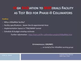
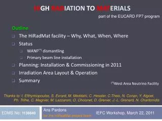
part of the EUCARD FP7 program. Outline The HiRadMat facility – Why, What, When, Where Status WANF (*) dismantling Primary beam line installation Planning: Installation & Commissioning in 2011 Irradiation Area Layout & Operation Summary. Hi gh Rad iation to Mat erials .

E N D
part of the EUCARD FP7 program • Outline • The HiRadMat facility – Why, What, When, Where • Status • WANF(*) dismantling • Primary beam line installation • Planning: Installation & Commissioning in 2011 • Irradiation Area Layout & Operation • Summary High Radiationto Materials (*)West Area Neutrino Facility Thanks to: I. Efthymiopoulos, S. Evrard, M. Meddahi, C. Hessler, C.Theis, N. Conan, Y. Algoet, Ph. Trilhe, C. Magnier, M. Lazzaroni, O. Choisnet, D. Grenier, J.-L. Grenard, N. Charitonidis Ans Pardons for the HiRadMat project team EDMS No: 1136640 IEFC Workshop, March 22, 2011
The HiRadMatFacility Why, What & When Why What When • Luminosity increases in particle accelerators materials of near-beam equipment must be able to withstand the higher beam intensity • Need for a facility to test materials in an intense pulsed beam to investigate damage effects from heat & radiation with increasing intensity. analyze the threshold of destructive effects to find material limitations • HiRadMat = Facility to study the impact of intense pulsed beams on materials • Thermal management (heating) & thermal shock (pressure waves) • Radiation damage to materials - change of mechanical properties • Beam extracted from SPS (450GeV/c): provides 1011 protons per bunch, 288 bunches per pulse, 30 pulses per user 1015 protons per user, ~2.4MJ/pulse • Beam size 0.1-0.5mm (1σ) at impact. • Aim for 2011: 3 users - LHC phase 2 collimator (jaw materials), tungsten powder (as high-power target for future neutrino beams), beam windows. • Interest expressed for > 2011: protection devices, machine components, material studies, irradiation tests of electronics. Ans Pardons
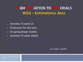
The HiRadMatFacility Where TT60 Beam SPS TI 2 TI2 LHC TNC (former WANF target hall) TT61 (to former West Area) TT66 new line Beam 50 m End of common part with TI 2 transfer line HiRadMat test objects Access to HiRadMat intrinsically linked to LHC (injection) Ans Pardons
The HiRadMatFacility Where & Location of main dismantling activities TNC HiRadMat User Experimental Area TI2 T9 TJ7 T1 Former beamline targets radiation • T9: former neutrino beam target:dismount target & collimators and install HRM beam dump in and behind former T9 shielding castle BA7 HiRadMat User Experimental Area B.846 TCC6 TNC TJ7 WANF target chamber With secondary beamline Ans Pardons T1 - former West Area primary target & shielding & MTR magnets: dismount TNC - former neutrino target hall with secondary beam elements: replace services, dismount beam elements & complete HRMbeam dump
Status – WANF dismantling General dismantling Hot objects & high remnant radiation dose Remote handling tools • Cameras on renovated crane and in TNC • Automatic hook for standard blocks • Shielded fork lift • Several custom-made hooks & lifting beams Shielding during intervention & transport Ans Pardons
Status - WANF dismantling Example 1: WANF Horn & collimator removal (*) Intersecting Storage Rings Horn and support manually dismounted from TNC and sent to waste storage in ISR(*) Collimator and support 80% remotely dismounted and sent to waste storage in ISR Ans Pardons
Status - WANF dismantling Example 2: T9 dismantling (transformation) ν-production target Copper downstream collimator blocks Steel upstream collimator Downstream monitor (*) Target External Dump • T9 target station (installed 1993, 5 years of beam) • T9: transformation to HiRadMat beam dump: 1. Remove target, all collimators & monitor 2. Replace upstream collimator with new collimator 3. Replace other items with TED(*)-type beam dump 4. Close shielding and complete HRM beam dump Ans Pardons
Status - WANF dismantling Target & upstream collimator Downstream collimator Upstream collimator 15 3.5 7.5 25 165 Dose rate (mSv/h) measuredat contact withtarget container and cradles (12.01.11) ν-production target • Dose rate near target and upstream collimator • Items designed in 1993 for remote removal! • Remote removal, transport to ISR in shielded containers or on shielded trailers Ans Pardons
Status - WANF dismantling Downstream collimator blocks dismantling: Challenges Dose rate (mSv/h) measuredinside and near the collimator (12.01.11) 60@ 5cm 20@ 40cm 1000 430 • Dose rate in & near copper collimator blocks Reminder: forbidden area if dose rate > 100mSv/h • The collimator blocks’ geometry brings several challenges • Each block (2.7t) has hot outer surface • Axis of 2 blocks is outside range of overhead crane • Items not designed for remote handling!!! • 4 threaded holes per block • 1993: installed manually with forklift, lifting rings and straps Ans Pardons
Status - WANF dismantling ALARA Level 3 committee Dismantling work took ~10 days, collective dose of ~1.2mSv Following > 100mSv/h dose rate measurement, the case of T9 dismantling was presented to the ALARA L3 committee Results & consequences: • Review took place of detailed dismantling procedure by CERN safety specialists from outside the project (M. Tavlet & P. Bonnal) • Detailed risk analysis established • Decision taken to NOT remove the copper blocks out of TNC (yet) • Blocks with handling plates will be placed in custom-build containers in a 40cm thick iron sarcophagus downstream TNC • The evacuation of the blocks from TNC will be carefully planned by EN/MEF & DGS/RP and executed in the “near” future (e.g. shut-down 2013) • Green light from reviewers and hierarchy obtained to start T9 dismantling on 2/2. Ans Pardons
Status –WANF dismantling Downstream collimator blocks dismantling: Solutions Minimise risk & dose personnel • Lifting & shielding plates fixed manually on copper blocks • Custom-made lifting beam takes 2 blocks at the time • Shielding in place for all manual interventions • Extensive tests on mock-up • Optimise tools • Define camera positions for handling • Training interveners Ans Pardons
Status –WANF dismantling T9 downstream collimator dismantling in pictures Moving upper blocks with fixed lifting plates Blocks in temporary storage location Sarcophagus with containers ready Fixing plates on lower blocks Separating blocks 21 Placing block in container Lifting test before closing roof Ans Pardons
Status - WANF Dismantling Waste management • Radioactive waste is treated in several steps: • Rough cleaning in WANF (specialized company ENDEL Nucléaire) • Removal from WANF TT61 TT4 • In TT4: thorough decontamination and disassembling • Volume reduction in RP waste workshop in building 573 • Convenient conditioning for long term storage • Long term storage in ISR TT4 WANF BA7 ISR 573 Disposal path Long term storage ISR Volume reduction x 10 Contaminated objects: Adapted closed containers
Status - Primary beamline installation Installation progress of TT66 beamline Summary table status mid March 2011 (upstream line TT60/TI2 is 100% installed) Ans Pardons
Planning 2011 Installation & commissioning Shutdown works: dismount air ducts, dismount horn, collimators & T9 target, install beamline magnets, install general services, ...) Short accesses (linked to LHC injection activity): install doors, beam instr., vacuum, align beam elements, ... • T9 transformed (no TED) • Beam line installed & elements connected(incl. beam instrumentation) • TED dump core and downstream muon dumps installed • Ventilation operational (challenge!) • Beam line under beam vacuum • Exp area in TNC installed & operational (cabling, services, ...) • Surface preparation lab & control room ready Ans Pardons
Planning 2011 Installation & commissioning • Installation & handling equipment & procedures ready, tested & approved • Downstream cool-down area ready Ans Pardons
Commissioning plans • Hardware commissioning on-going: powering tests, etc. • Dry runs to check the overall beam equipment functionality without beam (week 14):Control applications, interlock, magnets/power converters, beam instrumentation. • Commissioning of the facility with beam (weeks 20 and 21): • Tests with probe beams:Aperture checks, beam parameter checks, steering, beam size / focal point position adjustment, position / intensity stability, BI (calibration, etc.), controls, logging, interlocking tests, etc. • Some high intensity shots to check the consistency with the nominal beam intensity. Ans Pardons
Readiness 2011 Remaining work Dismantling 99% finished Beamline 90% installed, remaining part planned for week 13 Beam dump will be completed in week 19 Ventilation system will be ready for first user. Installation before week 20 unsure. Discussion on-going to allow limited amount of test pulses/protons without ventilation. Experimental area test tables designed & tested, production under way, will be ready for first user Cabling for test tables remains to be done during the next technical stops (weeks 13, 19&25). Installation sequence will be done such that the needs for2011 will be met before installation first user. Ans Pardons
Irradiation area layout Layout & concept Radiation Measurement Beam Focal Points: Beam Loss Monitors • 3 possible focal points for beam 3 positions for test stand • Geometry & services available to users on test stand: • Volume ~1.5x0.7x0.7 m³, weight up to 4 tons • Cooling circuit, electricity, neutral gas available • Signal connectors (e.g. for camera, motorization, beam instrumentation, vibration measurement, … ) • ~25m upstream: Patch panel to test signals/services before beam • ~100m downstream: cool-down storage area for test objects Ans Pardons
Irradiation area layout Design Small object, e.g. material sample Large object, e.g. LHC Collimator Test stand : base table in TNC and mobile table with test object (remote handling) comes from surface Interface between tables : remote / automatic plug-in connectors (water, power, signal) Check user system (motors, camera, laser, ...) before beam in TJ7, during beam only from surface control room Ans Pardons
Operation • Guidelines • (up to) 10 users/year, (up to) 1015 protons/user • This quota includes several pilot pulses during setup • Pilot pulses can be done in an almost transparent way to present operations • High-intensity pulses will be done in dedicated HiRadMat cycles impact on other SPS physics users • User selection panel will: (panel with experts from: radiation protection, safety, beam, physics goals, engineering, PS&SPS operation as well as external experts) • Review the beam requests, establish criteria for acceptance/rejection (e.g. scientific value, beam feasibility, safety concerns, impact to the facility,…) • Establish priority list of experiments with respect to the available beam time • Distribute beam time and schedule experiments Ans Pardons
Operation Operating procedure: first ideas A detailed and official “operating procedure” document will be written & released by the project team in due time A HiRadMat “brochure” will show what HiRadMat offers in services, signal, alignment, control room, observation equipment, beam type, ... Approval of user’s proposal by user selection panel Preparation of interface parts (windows, containers, observation equipment, motorised tables etc.) in collaboration with area engineers & designers Arrival at CERN of users ~2 weeks before beam: mounting test object on mobile table, alignment and test connectors in surface lab and control room During the week before beam (LHC technical stop): remote installation, remote test of signals, motorization, observation equipment, etc. Beam start. Observation and data taking from control room on surface. After beam tests: remote moving of mobile test table to cool-down area Later, possibly only during end-of-year shut-down: bringing test object back to surface (RP lab) Ans Pardons
Operation Activation dose rate after 1 user test – Fluka calculation results After 1 hour: <50000µSv/h (*)avg. at 40cm, detailed results available To TJ7 Test object Beam dump After 1 week: <5000µSv/h (*)avg. at 40cm, detailed results available 5 20 4000 15E3 50E3 µSv/h 270 1000 1.4 70 0.4 • Assumption: • Short SPS cycle, 1.98E12 p/s for 504 s (1e15 protons) • The beam hits the carbon jaw of a typical collimator • Activation dose near(*) test object after 1 hour/1 week cool-down Ans Pardons
Operation Background dose rate after a full year of operation – test object removed After 1 day: <100µSv/h After 1 month: <25µSv/h 20 50 100 0.2 2 5 0.6 0.1 µSv/h During annual shut-down: possible to intervene near test stands for repair or upgrade Assumption: 1016 protons over 1 year on a 15cm long copper test object, followed by removal of test object Background dose rate in TNC after 1 day / 1 month Ans Pardons
Summary 95% • Work done in 2010 and early 2011: • WANF dismounted • Primary beamline installed • Readiness for 2011: • Remaining works for week 13 & 19 well defined, prepared & planned • Ready for dry run week 14, commissioning week 20 • Ready for scheduled users from week 26 on • Planning for 2011: aim for 3 users w26, w32, w39 • “Operating procedure” document under way Ans Pardons
HiRadMat knocking at the door Thank you for listening – Any questions? Ans Pardons
Extra: Introduction Beam parameters Beam extracted from SPS (450GeV/c): provides 1011 protons per bunch, 300 bunches per pulse, 100 pulses per user and beam spot 0.5-2mm² at impact. Protons Heavy ions
Extra: Dismantling - transformation TED Geometry & materials
Extra: Dismantling lessons learnt from dismantling • Design new equipment with remote handling & waste disposal in mind • Collaboration with RP during design • Write future dismantling procedures now • Update technical drawings “as-built” • Largest dismantling dose from cables, cleaning, etc. • Use specialised company & invest in tools • Install new cables, trays, lights etc. with dismantling in mind
Extra: Dismantling origin of dose during dismantling WANF Add dismantling T9 in Jan. 2011: ~1200 µSv) Lesson learnt: also install services with easy future dismantling in mind! (largest doses are not taken on the most complex/radioactive objects)
Extra: Dismantling 31 T1 removal Example: Dismantling T1 target station & MTR magnets September 2009 January 2011 February 2011
Extra: Irradiation area Prototypes & Tests Signals connector Water connector Base table with alignment plug-ins Alignment plug-ins Repeatability test of alignment & automatic connectors successful design approved In 2011: Need 1 base table and 3 mobile tables Installation base table planned week 19, mobile tables under construction, ready for first user Ans Pardons
Extra: Operation Activation dose rate after 1 user test
Extra: Operation Users • First: short cool-down period before dismounting • Then: taken out to surface or moved to underground downstream cool-down area Warning! Non-contractual test object images. Pictures may differ from actual product (a lot). Ans Pardons
Extra: Operation Measures because of radiation dose rates Before beam After beam • Possible (RP approval) to intervene in TNC for “upgrade” of user’s services, limited repair works, ... End-of-year shut-down TNC TJ7 Alignment at surface on pre-aligned base table Remote handling of test stand, crane operator in TJ7 Access to TJ7 before beam, rack for tests of signals, services, motorisation, observation equipment No access to TNC (exception only with RP approval) Cool-down area for equipment downstream TNC Re-use of mobile tables only if negligible dose rate Ans Pardons
Extra: Operation Future users • Future users already interested in using HiRadMat • Collimator phase 2 (prototyping work) • LHC beam dump entrance window robustness • Studies of protection devices and windows (TE-ABT) • Vacuum chamber coatings for electron cloud mitigation • R2E teams - irradiation facility – radiation damage • BLM developments • LARP Rotatable Collimator Robustness Test (SLAC) • Radiation tolerance tests (EN-STI) • ISOLDE – Target and Ion Source Development
Extra beamline Beam TI 2 TT60 TT66 Experimental area 25 m Christoph Hessler
Beam Line Status (March 2011) Beam TI 2 TT60 upstream chicane: • All magnets installed and aligned. • Vacuum system installed and under vacuum. • TT60 back in operation. TT60 TT66 Experimental area 25 m Christoph Hessler
Beam Line Status (March 2011) Beam TI 2 TT60 TI 2: • TBSE and additional BPMs installed. • Re-installation completed and under vacuum. • TI 2 back in operation. TT66 Experimental area 25 m Christoph Hessler
Beam Line Status (March 2011) Beam TI 2 TT60 TT66 TT66 in TCC6: • Installation completed in TCC6: • Magnets/BI/vacuum system installed. • Cables pulled and connected. • Vacuum: Leak tested up to QTLF.660300 at the end of TCC6. Experimental area 25 m Christoph Hessler
Beam Line Status (March 2011) Beam TI 2 TT60 TT66 Experimental area 25 m Christoph Hessler
Beam Line Status (March 2011) Beam TI 2 TT66 in TJ7/TNC: • All magnets and most BI installed (only last BTV and BPKG missing). • Alignment work almost completed. • Installation of vacuum system on-going. • To be under vacuum at end of next TS. TT60 TT66 Experimental area 25 m Christoph Hessler