Download
1 / 18
180 likes | 345 Vues
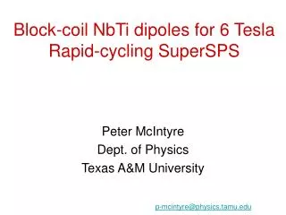
Block-coil NbTi dipoles for 6 Tesla Rapid-cycling SuperSPS. Peter McIntyre Dept. of Physics Texas A&M University. p-mcintyre@physics.tamu.edu. The goal of our R&D: Dipoles for future hadron colliders. TAMU4: 14.1 T, 4 x 3 cm 2 aperture 28 cm 2 superconductor

E N D
Block-coil NbTi dipoles for 6 Tesla Rapid-cycling SuperSPS Peter McIntyre Dept. of Physics Texas A&M University p-mcintyre@physics.tamu.edu
The goal of our R&D: Dipoles for future hadron colliders TAMU4: 14.1 T, 4 x 3 cm2 aperture 28 cm2 superconductor Collider-quality field, suppress p.c. multipoles LHC Tripler: 24 T, 56 mm aperture Windings = Bi-2212 inner, Nb3Sn outer
Designing dipoles with Nb3Sn The challenges • The conductor is fragile – strain < 0.5% • High field limit would be imposed by Lorentz stress • Filaments are large – snap-back too large The solutions • Block-coil geometry • Stress management • Hydraulic preload • Flux-plate suppression of snap-back
Offload stress from windings to structure stress (PSI) in structure @ 14 T stress (PSI) in coils only @ 14 T
Provide overall preload using expansion bladders • Flux return split vertically, serves as piston • Bladders filled with low-melt Wood’s metal • Bladders located between flux return and Al shell • 2,000 psi pressure delivers full-field Lorentz load • In cooldown, Al shell delivers additional preload
Suppression of multipoles from persistent current magnetization • Persistent magnetization is generated from current loops within the filaments, • Magnetization relaxes via BIC’s, then snap-back
The steel flux plate redistributes flux to suppress multipoles 0.5 T 12 T
Multipoles with Persistent Currents 5x suppression of p.c. sextupole – compensates for larger filament size
The Texas A&M program • TAMU1(6.5 T) • evaluate block-coil geometry, winding and impregnation strategies using NbTi model - tested to short sample • TAMU2(5.2 T) • single-pancake mirror magnet with ITER Nb3Sn conductor - completed, ready for testing • TAMU3(13.5 T) • double-pancake model with 2.4 kA/mm2 conductor - beginning fabrication • TAMU4(14.1 T ) • complete Nb3Sn dipole with 4x3 cm bore
TAMU1 • Model dipole to study block coil geometry: cable preparation, winding techniques, impregnation: treat exactly according to the design for Nb3Sn.
Testing of TAMU1 Winding voltages during quench
AC losses 1 T/s 1.5 T/s TAMU1 is the first fully impregnated NbTi dipole made in modern times. It operated to short sample without training and exhibits good AC performance. This result demonstrates that the helium access thought essential for NbTi stability is not necessary, provided that stress is managed so as to prevent conductor motion and friction heat.
TAMU2: our entry into Nb3Sn technology TAMU2: 1 single-pancake winding mirror geometry, ITER superconductor 5.6 T short-sample bore field
Coil winding Inconel ribs, laminar springs transfer stress between windings. Ti mandrel to preserve preload through cooldown.
Inject to LHC from SuperSPS • For luminosity upgrade of LHC, one option is to replace the SPS and PS with a rapid-cycling superconducting injector chain. • 1 TeV in SPS tunnel 1.25 T in hybrid dipole: flux plate is unsaturated, suppression of snap-back multipoles at injection. • SuperSPS needs 6 T field, ~10 s cycle time for filling Tripler >1 T/s ramp rate
Again block-coil geometry is optimum! In cos dipole, cables are oriented on an azimuthal arch: Result: maximum induced current loop, maximum AC losses In block-coil dipole, cables are oriented vertically: Result: minimum induced current loop, minimum AC losses
Preliminary design for Super-SPS dipole Vertical cable orientation to suppress AC losses Flux plate to suppress magnetization multipoles at injection 6 T short-sample field (to allow for AC loss degradation) LHC NbTi strand (wider cable to optimize geometry, minimize inductance) We are modeling AC losses, expect to be low. Flux plate suppresses multipoles from persistent currents, AC-induced currents (flux plate must be laminated)