Chapter 3 Introduction to WCDMA
660 likes | 952 Vues
Chapter 3 Introduction to WCDMA. 3.2 Summary of the Main Parameters in WCDMA 3.3 Spreading and Despreading 3.4 Multipath Radio Channels and Rake Reception 3.5 Power Control 3.6 Softer and Soft Handovers. 3.2 Summary of the Main Parameters in WCDMA.

Chapter 3 Introduction to WCDMA
E N D
Presentation Transcript
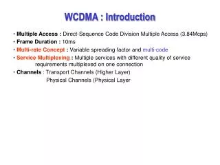
3.2 Summary of the Main Parameters in WCDMA 3.3 Spreading and Despreading 3.4 Multipath Radio Channels and Rake Reception 3.5 Power Control 3.6 Softer and Soft Handovers
(1) Multiple access method • WCDMA is a wideband Direct-Sequence Code Division Multiple Access (DS-CDMA) system • user information bits are spread over a wide bandwidth by • multiplying user data with quasi-random bits (called chips) derived from CDMA spreading codes • in order to support very high bit rates (up to 2Mbps), the use of a variable spreading factor and multicode connections is supported
(2) Duplexing method • WCDMA supports both FDD and TDD modes of operation • Frequency Division Duplex (FDD) • separate 5 MHz carrier frequencies are used for uplink and downlink, respectively • Time Division Duplex (TDD) • only one 5 MHz is timeshared between uplink and downlink
(3) Basic station synchronization • WCDMA supports the operation of asynchronous base stations • no need for a global time reference such as a GPS • deployment of indoor and micro base stations is easier when no GPS signal needs to be received
(4) Chip rate • chip rate of 3.84 Mcps leads to a carrier bandwidth (channel bandwidth) of approximately 5 MHz • chip:the length of time to transmit either a "0" or a "1" in a binary pulse code • chip rate:number of chips per second • DS-CDMA systems with a bandwidth of about 1 MHz (narrowband CDMA systems) • wide carrier bandwidth of WCDMA supports high user data rates
(5) Frame length & slot length • frame length • 10ms (1 frame length = 38400 chips) • slot length • 15 slots /frame (1 slot length = 2560 chips)
(6) Service multiplexing • multiple services with different quality of service requirements multiplexed on one connection
(7) Multirate concept • use a variable spreading factor and multicode to support very high bit rates (up to 2 Mbps) • multicode • in multicode CDMA systems, each user can be provided with multiple spreading codes of fixed length, depending on users' rate requests • motivations for multicode CDMA • increase the information rate over a given spread bandwidth • allow for the flexibility of multiple data rates
(8) Detection • WCDMA employs coherent detection(連續偵測) on uplink and downlink based on the use of pilot symbols(導引符號) or common pilot(共用導引) • coherent detection (coherent demodulation) • a method of recovering the original signal that requires an exactly same carrier frequency and phase (propagation delay causes carrier-phase offset) as those used in the transmitting end • the received signal is mixed, in some type of nonlinear device, with a signal from a local oscillator, to produce an intermediate frequency, from which the modulating signal is recovered (detected)
use of coherent detection on uplink will result in an overall increase of coverage and capacity on the uplink
(9) Multiuser detection and smart antennas • supported by the standard • deployed by network operator as a system option to increase capacity and/or coverage
Smart antennas (also known as adaptive array antennas, multiple antennas and recently MIMO) • antenna arrays with smart signal processing algorithms used to identify spatial signal signature such as the direction of arrival (DOA) of the signal, and use it to calculate beamforming vectors, to track and locate the antenna beam on the mobile/target • the antenna could optionally be any sensor • smart antenna techniques are used notably in acoustic(聲波的) signal processing, track and scan RADAR, radio astronomy (天文學) and radio telescopes (無線電天文望遠鏡), and mostly in cellular systems like W-CDMA and UMTS
Other WCDMA Features • WCDMA supports highly variable user data rates, in other words the concept of obtaining Bandwidth on Demand (BoD) • the user data rate is kept constant during each 10 ms frame • however, the data capacity among users can change from frame to frame • this fast radio capacity allocation will typically be controlled by the network to achieve optimum throughput for packet data services
Handovers • WCDMA is designed to be deployed in conjunction with GSM • handovers between GSM and WCDMA are supported to leverage GSM coverage
3.3 Spreading and Despreading • Spread-spectrum transmission • a technique in which the user’s original signal is transformed into another form that occupies a larger bandwidth than the original signal would normally need • the original data sequence is binary multiplied with a spreading code that typically has a much larger bandwidth than the original signal • the bits in the spreading code are called chips to differentiate them from the bits in the data sequence, which are called symbols
each user has its own spreading code • the identical code is used in both transformations on each end of the radio channel • spreading the original signal to produce a wideband signal • despreading the wideband signal back to the original narrowband signal
the ratio between the transmission bandwidth and the original bandwidth is called the processing gain • also known as the spreading factor (SF) • this ratio simply means how many chips are used to spread one data symbol • in the UTRAN, the spreading-factor values can be between 4 and 512 • in the TDD mode also SF=1 is allowed • the lower the spreading factor, the more payload data a signal can convey on the radio interface
Spreading and despreading operation • user data is assumed to be a BPSK-modulated (Binary Phase Shift Keying) bit sequence of rate R • user data bits are assumed the values of 1 or -1 • spreading operation • the multiplication of each user data bit with a sequence of 8 code bits, called chips (the spreading factor is 8) • the resulting spread data is at a rate of 8 × R • despreading operation • multiply the spread user data/chip sequence, bit duration by bit duration, with the very same 8 code chips as we used during the spreading of these bits • as shown, the original user bit sequence has been recovered perfectly
the increase of the signaling rate by a factor of 8 corresponds to a widening (by a factor of 8) of the occupied spectrum of the spread user data signal • despreading restores a bandwidth proportional to R for the signal
Rake Receiver • Rake receiver • a radio receiver designed to counter the effects of multipath fading • uses several "sub-receivers" (called fingers) each delayed slightly , that is, several correlators each assigned to a different multipath component • each component is decoded independently, but at a later stage combined in order to make the most use of the different transmission characteristics of each transmission path
the digital section of a CDMA receiver which permits the phone (or cell) to separate out the relevant signal from all the other signals • can receive multiple signal sources and add them together using multiple fingers • Rake receivers are common in a wide variety of radio devices including mobile phones and wireless LAN equipment
Digitized input samples • received from RF (Radio Frequency) front-end circuitry in the form of I and Q branches • Code generators and correlator • perform the despreading and integration to user data symbols • Channel estimator and phase rotator • channel estimator uses the pilot symbols[導引符號] for estimating the channel state which will then be removed by the phase rotator from the received symbols Phase rotator: a device used in radio astronomy [天文學] to adjust the phase of an incoming signal.
Delay equliser • the delay is compensated for the difference in the arrival times of the symbols in each finger • Rake combiner • sums the channel compensated symbols, thereby providing multipath diversity against fading
Matched filter • used for determining and updating the current multipath delay profile of the channel • this measured and possibly averaged multipath delay profile is then used to assign the Rake fingers to the largest peaks
3.5 Power Control • Fast power control is in particular on the uplink • without it, a single overpowered mobile could block a whole cell
Power control in WCDMA • open-loop power control • close-loop power control • inner-loop power control • outer-loop power control
Open Loop Power Control in WCDMA • Open loop power control in WCDMA • attempt to make a rough estimation of path loss by measuring downlink beacon signal • problem • far too inaccurate • fast fading is essentially uncorrelated between uplink and downlink due to large frequency separation of uplink and downlink band of WCDMA FDD mode • open-loop power control is used in WCDMA to provide a coarse initial power setting of MS at the beginning of a connection
Inner-Loop Power Control in WCDMA • Inner-loop power control in WCDMA uplink • BS performs frequent estimates of the received Signal-to-Interference Ratio (SIR) and compares it to a target SIR • if the measured SIR is higher than the target SIR, BS will command MS to lower the power • if SIR is too low, it will command MS to increase its power
measure–command–react cycle • executed at a rate of 1500 times per second (1.5 kHz) for each MS • faster than any significant change of path loss could possibly happen • faster than the fast Rayleigh fading speed for low to moderate mobile speeds • inner-loop power control • prevent any power imbalance among all the uplink signals received at BS
Inner-loop power control in WCDMA downlink • adopt the same techniques as those used in uplink • operate at a rate of 1500 times per second • no near–far problem due to “one cell to many mobiles” scenario
downlink closed-loop power control • provide a marginal amount of additional power to MS at the cell edge as they suffer from increased other-cell interference • enhance weak signals caused by Rayleigh fading when other error-correcting methods doesn’t work effectively
Figure 3.8 depicts closed loop transmission power control in CDMA • MS1 and MS2 operate within the same frequency, separable at the BS only by their respectivespreading codes • it may happen that MS1 at the cell edge suffers a path loss, say 70 dB above that of MS2 which is near the BS
if there were no power control mechanism for MS1 and MS2 to the same level at BS • MS2 could easily overshout MS1 and thus block a large part of the cell, giving rise to the near–far problem of CDMA
Figure 3.9 shows how uplink closed loop power control works on a fading channel at low speed
Outer-Loop Power Control in WCDMA • Outer-loop power control in WCDMA • adjusts the target SIR setpoint in BS according to the individual radio link quality requirement, usually defined as bit error rate (BER) or block error rate (BLER) • the required SIR or BLER depends on the mobile speed, multipath profile, and data rate • should the transmission quality is decreasing, the RNC will command Node B to increase the target SIR • outer-loop power control is implemented in RNC because there might be soft handover combining
Why should there be a need for changing the target SIR setpoint? • the required SIR for, say, BLER = 1% depends on mobile speed and multipath profile • if one were to set the target SIR setpoint for high mobile speeds, one would waste much capacity for those connections at low speeds • the best strategy is to let the target SIR setpoint float around the minimum value that just fulfils the required target quality
The target SIR setpoint will change over time as the speed and propagation environment changes (Figure 3.10) • Outer loop control is typically implemented by • having BS tag each uplink user data frame with a frame reliability indicator, such as a CRC (Cyclic Redundancy Check) result obtained during decoding of that particular user data frame
should the frame quality indicator shows the transmission quality is decreasing • RNC will command BS to increase target SIR setpoint