Download
1 / 52
3.37k likes | 8.76k Vues
Flat Belt Drives. 1. Introduction The belts or ropes are used to transmit power from one shaft to another by means of pulleys which rotate at the same speed or at different speeds. The amount of power transmitted depends upon the following factors : 1. The velocity of the belt.

E N D
1. Introduction The belts or ropes are used to transmit power from one shaft to another by means of pulleys which rotate at the same speed or at different speeds. The amount of power transmitted depends upon the following factors : 1. The velocity of the belt. 2. The tension under which the belt is placed on the pulleys. 3. The arc of contact between the belt and the smaller pulley. 4. The conditions under which the belt is used. Note : (a) The shafts should be properly in line to insure uniform tension across the belt section. (b) The pulleys should not be too close together, in order that the arc of contact on the smaller pulley may be as large as possible.
(c) The pulleys should not be so far apart as to cause the belt to weigh heavily on the shafts, thus increasing the friction load on the bearings. (d) A long belt tends to swing from side to side, causing the belt to run out of the pulleys, which in turn develops crooked spots in the belt. (e) The tight side of the belt should be at the bottom, so that whatever sag is present on the loose side will increase the arc of contact at the pulleys. ( f ) In order to obtain good results with flat belts, the maximum distance between the shafts should not exceed 10 metres and the minimum should not be less than 3.5 times the diameter of the larger pulley.
2. Selection of a Belt Drive • Following are the important factors in selection of a belt drive: • Speed of the driving and driven shafts • Speed reduction ratio • Power to be transmitted • Centre distance between the shafts • Positive drive requirements • Shafts layout • Space available • Service conditions • 3. Types of Belt Drives • The belt drives are usually classified into the following three groups: • Light drives. These are used to transmit small powers at belt speeds up to about 10 m/s as in agricultural machines and small machine tools. • Medium drives. These are used to transmit medium powers at belt speeds over 10 m/s but up to 22 m/s, as in machine tools. • Heavy drives. These are used to transmit large powers at belt speeds above 22 m/s as in compressors and generators
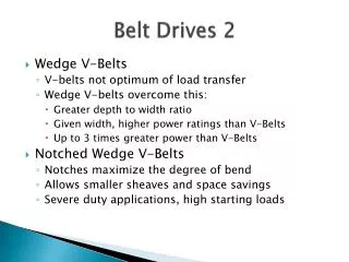
4. Types of Belts • The following are the common types of belts : • Flat belt. The flat belt as shown in Fig. 1 (a), is mostly used in the factories and workshops, where a moderate amount of power is to be transmitted, from one pulley to another when the two pulleys are not more than 8 metres apart. • V- belt. The V-belt as shown in Fig.1 (b), is mostly used in the factories and workshops, where a great amount of power is to be transmitted, from one pulley to another, when the two pulleys are very near to each other. • Circular belt or rope. The circular belt or rope as shown in Fig. 1 (c) is mostly used in the factories and workshops, where a great amount of power is to be transmitted, from one pulley to another, when the two pulleys are more than 8 metres apart. Figure 1 Types of belts
5. Material used for Belts The material used for belts and ropes must be strong, flexible, and durable. It must have a high coefficient of friction. The belts, according to the material used, are classified as follows: Leather belts. The best leather belts are made from 1.2 metres to 1.5 metres long strips cut from either side of the back bone of the top grade steer hides. The hair side of a belt should be in contact with the pulley surface as shown in Fig. 2. The belts are specified according to the number of layers e.g. single, double or triple ply and according to the thickness of hides used e.g. light, medium or heavy. Cotton or fabric belts. Most of the fabric belts are made by folding convass or cotton duck to three or more layers (depending upon the thickness desired) and stitching together. The cotton belts are cheaper and suitable in warm climates, in damp atmospheres and in exposed positions. Since the cotton belts require little attention, therefore these belts are mostly used in farm machinery, belt conveyor etc. Figure 2 Leather belts
Rubber belt. The rubber belts are made of layers of fabric impregnated with rubber composition and have a thin layer of rubber on the faces. These belts are very flexible but are quickly destroyed if allowed to come into contact with heat, oil or grease. One of the principle advantage of these belts is that they may be easily made endless. These belts are found suitable for saw mills, paper mills where they are exposed to moisture. Balata belts. These belts are similar to rubber belts except that balata gum is used in place of rubber. These belts are acid proof and water proof and it is not effected by animal oils or alkalies. The balata belts should not be at temperatures above 40°C because at this temperature the balata begins to soften and becomes sticky. The strength of balata belts is 25 per cent higher than rubber belts.
6. Working Stresses in Belts The ultimate strength of leather belt varies from 21 to 35 MPa and a factor of safety may be taken as 8 to 10. However, the wear life of a belt is more important than actual strength. It has been shown by experience that under average conditions an allowable stress of 2.8 MPa or less will give a reasonable belt life. An allowable stress of 1.75 MPa may be expected to give a belt life of about 15 years. 7. Density of Belt Materials The density of various belt materials are given in the following table. Table 1. Density of belt materials 8. Belt Speed When the speed of belt increases, the centrifugal force increases which tries to pull the belt away from the pulley. This reduces the power transmitted by the belt. For the efficient transmission of power, the belt speed 20 m/s to 22.5 m/s may be used.
9. Coefficient of Friction Between Belt and Pulley The coefficient of friction between the belt and the pulley depends upon the following factors: The material of belt The material of pulley The slip of belt The speed of belt According to C.G. Barth, the coefficient of friction (μ) for oak tanned leather belts on cast iron pulley, at the point of slipping, is given by the following relation, i.e. where v = Speed of the belt in metres per minute.
The following table shows the values of coefficient of friction for various materials of belt and pulley. Table 1.2. Coefficient of friction between belt and pulley.
10. Standard Belt Thicknesses and Widths • The standard flat belt thicknesses are 5, 6.5, 8, 10 and 12 mm. The preferred values of thicknesses are as follows: • 5 mm for nominal belt widths of 35 to 63 mm • 6.5 mm for nominal belt widths of 50 to 140 mm • 8 mm for nominal belt widths of 90 to 224 mm • 10 mm for nominal belt widths of 125 to 400 mm • 12 mm for nominal belt widths of 250 to 600 mm. • The standard values of nominal belt widths are in R10 series, starting from 25 mm up to 63 mm and in R 20 series starting from 71 mm up to 600 mm. Thus, the standard widths will be 25, 32, 40, 50, 63, 71, 80, 90, 100, 112, 125, 140, 160, 180, 200, 224, 250, 280, 315, 355, 400, 450, 500, 560 and 600 mm. • 11. Belt Joints • The various types of joints are : • Cemented joint (Fig. 3a) • Laced joint (known as straight-stitch raw hide laced joint), Fig. 3b dan 3c • Hinged joint (Fig. 3d)
12. Types of Flat Belt Drives The power from one pulley to another may be transmitted by any of the following types of belt drives. Open belt drive. The open belt drive, as shown in Fig. 4, is used with shafts arranged parallel and rotating in the same direction. Fig. 4. Open belt drive.
Crossed or twist belt drive. The crossed or twist belt drive, as shown in Fig. 5, is used with shafts arranged parallel and rotating in the opposite directions. The shafts should be placed at a maximum distance of 20 b, where b is the width of belt and the speed of the belt should be less than 15 m/s. Fig. 5. Crossed or twist belt drive.
Quarter turn belt drive. The quarter turn belt drive (also known as right angle belt drive) as shown in Fig. 6 (a), is used with shafts arranged at right angles and rotating in one definite direction. A quarter turn belt drive with a guide pulley, as shown in Fig. 6 (b). In order to prevent the belt from leaving the pulley, the width of the face of the pulley should be greater or equal to 1.4 b, where b is width of belt. Fig. 6
Belt drive with idler pulleys. A belt drive with an idler pulley (also known as jockey pulley drive) as shown in Fig. 7 and 8, is used with shafts arranged parallel and when an open belt drive can not be used due to small angle of contact on the smaller pulley. Fig. 7. Belt drive with single idler pulley. Fig. 8. Belt drive with many idler pulleys.
Compound belt drive. A compound belt drive as shown in Fig. 9, is used when power is transmitted from one shaft to another through a number of pulleys. Fig. 9. Compound belt drive.
Stepped or cone pulley drive. A stepped or cone pulley drive, as shown in Fig. 10, is used for changing the speed of the driven shaft while the main or driving shaft runs at constant speed. Fast and loose pulley drive. A fast and loose pulley drive, as shown in Fig. 11, is used when the driven or machine shaft is to be started or stopped whenever desired without interferring with the driving shaft. Fig. 10. Stepped or cone pulley drive Fig. 11. Fast and loose pulley drive
13. Velocity Ratio of a Belt Drive It is the ratio between the velocities of the driver and the follower or driven. Let d1= Diameter of the driver, d2= Diameter of the follower, N1= Speed of the driver in r.p.m., N2= Speed of the follower in r.p.m., ∴ Length of the belt that passes over the driver, in one minute = π d1 N1 Similarly, length of the belt that passes over the follower, in one minute = π d2 N2 Since the length of belt that passes over the driver in one minute is equal to the length of belt that passes over the follower in one minute, therefore ∴ π d1 N1 = π d2 N2 and velocity ratio, When thickness of the belt (t) is considered, then velocity ratio,
Notes : The velocity ratio of a belt drive may also be obtained as discussed below: We know that the peripheral velocity of the belt on the driving pulley, and peripheral velocity of the belt on the driven pulley, When there is no slip, then ν1 = ν2. In case of a compound belt drive as shown in Fig. 9, the velocity ratio is given by
14. Slip of the Belt If the forward motion of the driver without carrying the belt with it. This is called slip of the belt and is generally expressed as a percentage. The result of the belt slipping is to reduce the velocity ratio of the system. As the slipping of the belt is a common phenomenon, thus the belt should never be used where a definite velocity ratio is of importance (as in the case of hour, minute and second arms in a watch). Let s1 % = Slip between the driver and the belt s2 % = Slip between the belt and follower ∴ Velocity of the belt passing over the driver per second,
and velocity of the belt passing over the follower per second Substituting the value of ν from equation (i), we have If thickness of the belt (t) is considered, then
15. Creep of Belt When the belt passes from the slack side to the tight side, a certain portion of the belt extends and it contracts again when the belt passes from the tight side to the slack side. Due to these changes of length, there is a relative motion between the belt and the pulley surfaces. This relative motion is termed as creep. The total effect of creep is to reduce slightly the speed of the driven pulley or follower. Considering creep, the velocity ratio is given by Where : σ1 and σ2 = Stress in the belt on the tight and slack side respectively, and E = Young’s modulus for the material of the belt. Note: Since the effect of creep is very small, therefore it is generally neglected.
Example 1. An engine running at 150 r.p.m. drives a line shaft by means of a belt. The engine pulley is 750 mm diameter and the pulley on the line shaft is 450 mm. A 900 mm diameter pulley on the line shaft drives a 150 mm diameter pulley keyed to a dynamo shaft. Fine the speed of dynamo shaft, when 1. there is no slip, and 2. there is a slip of 2% at each drive. Solution. Given : N1 = 150 r.p.m. ; d1 = 750 mm ; d2 = 450 mm ; d3 = 900 mm ; d4 = 150 mm ; s1 = s2 = 2%. The arrangement of belt drive is shown in Fig. 12. Let N4 = Speed of the dynamo shaft. Fig. 12
1. When there is no slip 2. When there is a slip of 2% at each drive
16. Length of an Open Belt Drive In an open belt drive, both the pulleys rotate in the same direction as shown in Fig.13. Fig. 13. Open belt drive. Let r1 and r2 = Radii of the larger and smaller pulleys, x = Distance between the centres of two pulleys (i.e. O1O2), and L = Total length of the belt.
Let the belt leaves the larger pulley at E and G and the smaller pulley at F and H as shown in Fig.13. Through O2 draw O2M parallel to FE. From the geometry of the figure, we find that O2M will be perpendicular to O1E. Let the angle MO2O1 = α radians. We know that the length of the belt, L = Arc GJE + EF + Arc FKH + HG = 2 (Arc JE + EF + Arc FK) ...(i) From the geometry of the figure, we also find that Since the angle α is very small, therefore putting Similarly,
Expanding this equation by binomial theorem, we have Substituting the values of arc JE from equation (iii), arc FK from equation (iv) and EF fromequation (v) in equation (i), we get
17 Length of a Cross Belt Drive In a cross belt drive, both the pulleys rotate in the opposite directions as shown in Fig. 14. Let r1 and r2 = Radii of the larger and smaller pulleys, x = Distance between the centres of two pulleys (i.e. O1O2 ), and L = Total length of the belt. Let the belt leaves the larger pulley at E and G and the smaller pulley at F and H. Through O2 draw O2M parallel to FE. From the geometry of the figure, we find that O2M will be perpendicular to O1E. Let the angle MO2O1 = α radians. We know that the length of the belt, L = Arc GJE + EF + Arc FKH + HG = 2 (Arc JE + FE + Arc FK) ...(i) Fig.14. Crossed belt drive.
From the geometry of the figure, we find that Since the angle α is very small, therefore putting Similarly, and
Expanding this equation by binomial theorem, we have Substituting the values of arc JE from equation (iii), arc FK from equation (iv) and EF from equation (v) in equation (i), we get,
Substituting the value of from equation (ii), we get
18 Power Transmitted by a Belt The driving pulley pulls the belt from one side and delivers it to the other side. It is thus obvious that the tension on the former side (i.e. tight side) will be greater than the latter side (i.e. slack side) as shown in Fig. 15. T1, T2 = Tensions in the tight side and slack side of the belt respectively in newtons R1, r2 = Radii of the driving and driven pulleys respectively in metres, ν = Velocity of the belt in m/s. The effective turning (driving) force at the circumference of the driven pulley or follower is the difference between the two tensions (i.e. T1 – T2). Fig. 15. Power transmitted by a belt.
∴ Work done per second = (T1 – T2) ν N-m/s and power transmitted = (T1 – T2) ν W ... (∴ 1 N-m/s = 1W) A little consideration will show that torque exerted on the driving pulley is (T1 – T2) r1. Similarly, the torque exerted on the driven pulley is (T1 – T2) r2. 19 Ratio of Driving Tensions for Flat Belt Drive Consider a driven pulley rotating in the clockwise direction as shown in Fig. 16. Let T1 = Tension in the belt on the tight side, T2 = Tension in the belt on the slack side, and θ = Angle of contact in radians (i.e. angle subtended by the arc AB, along which the belt touches the pulley, at the centre). Now consider a small portion of the belt PQ, subtending an angle δθ at the centre of the pulley as shown in Fig. 16.
The belt PQ is in equilibrium under the following forces: 1. Tension T in the belt at P, 2. Tension (T + δT) in the belt at Q, 3. Normal reaction RN, and 4. Frictional force F = μ × RN, where μ is the coefficient of friction between the belt and pulley. Fig. 16. Ratio of driving tensions for flat belt.
Resolving all the forces horizontally, we have (i) Since the angle δθ is very small, therefore putting sin δθ/2 = δθ/2 in equation (i), we have (ii) Now resolving the forces vertically, we have (iii) Since the angle δθ is very small, therefore putting cosδθ/2 = 1 in equation (iii), we have (iv)
Equating the values of RN from equations (ii) and (iv), we get Integrating the above equation between the limits T2 and T1 and from 0 to θ, we have (v) The equation (v) can be expressed in terms of corresponding logarithm to the base 10, i.e.
Notes : While determining the angle of contact, it must be remembered that it is the angle of contact at the smaller pulley, if both the pulleys are of the same material. We know that ... (for open belt drive) ... (for cross-belt drive) ∴ Angle of contact or lap, ...(for open belt drive) ... (for cross-belt drive) When the pulleys are made of different material (i.e. when the coefficient of friction of the pulleys or the angle of contact are different), then the design will refer to the pulley for which μ.θ is small.
20 Centrifugal Tension The tension caused by centrifugal force is called centrifugal tension. At lower belt speeds (less than 10 m/s), the centrifugal tension is very small, but at higher belt speeds (more than 10 m/s), its effect is considerable and thus should be taken into account. Consider a small portion PQ of the belt subtending an angle dθ at the centre of the pulley, as shown in Fig. 18. m = Mass of belt per unit length in kg, v = Linear velocity of belt in m/s, r = Radius of pulley over which the belt runs in metres, and TC = Centrifugal tension acting tangentially at P and Q in newtons. We know that length of the belt PQ = r.dθ and mass of the belt PQ = m.r.dθ ∴ Centrifugal force acting on the belt PQ, Fig. 18. Centrifugal tension.
The centrifugal tension TC acting tangentially at P and Q keeps the belt in equilibrium. Now resolving the forces (i.e. centrifugal force and centrifugal tension) horizontally, we have (i) Since the angle dθ is very small, therefore putting in equation (i), we have Notes : When centrifugal tension is taken into account, then total tension in the tight side, and total tension in the slack side,
2. Power transmitted, ...(in watts) ... (same as before) Thus we see that the centrifugal tension has no effect on the power transmitted. 3. The ratio of driving tensions may also be written as where Tt1 = Maximum or total tension in the belt.
21 Maximum Tension in the Belt A little consideration will show that the maximum tension in the belt (T ) is equal to the total tension in the tight side of the belt (Tt1). Let σ = Maximum safe stress, b = Width of the belt, and t = Thickness of the belt. We know that the maximum tension in the belt, T = Maximum stress × Cross-sectional area of belt = σ.b.t When centrifugal tension is neglected, then T (or Tt1) = T1, i.e. Tension in the tight side of the belt. When centrifugal tension is considered, then T (or Tt1) = T1 + TC
22 Condition for the Transmission of Maximum Power The power transmitted by a belt, P = (T1 – T2) v (i) where : T1 = Tension in the tight side in newtons, T2 = Tension in the slack side in newtons, and ν = Velocity of the belt in m/s. Ratio of driving tensions is (ii) Substituting the value of T2in equation (i), we have (iii) where :
We know that T1 = T – TC where : T = Maximum tension to which the belt can be subjected in newtons, and TC = Centrifugal tension in newtons. Substituting the value of T1 in equation (iii), we have For maximum power, differentiate the above expression with respect to v and equate to zero, i.e. It shows that when the power transmitted is maximum, 1/3rd of the maximum tension is absorbed as centrifugal tension.
Notes : We know that T1 = T – TC and for maximum power, From equation (iv), we find that the velocity of the belt for maximum power,
23 Initial Tension in the Belt When the pulleys are stationary, the belt is subjected to some tension, called initial tension. The increased tension in one side of the belt is called tension in tight side and the decreased tension in the other side of the belt is called tension in the slack side. Let T0 = Initial tension in the belt, T1 = Tension in the tight side of the belt, T2 = Tension in the slack side of the belt, and α = Coefficient of increase of the belt length per unit force. The increase of tension in the tight side = T1 – T0 and increase in the length of the belt on the tight side = α (T1 – T0) (i) Similarly, decrease in tension in the slack side = T0 – T2 and decrease in the length of the belt on the slack side = α (T0 – T2) (ii)
Assuming that the belt material is perfectly elastic such that the length of the belt remains constant, when it is at rest or in motion, therefore increase in length on the tight side is equal to decrease in the length on the slack side. Thus, equating equations (i) and (ii), we have α (T1 – T0) = α (T0 – T2) or T1 – T0 = T0 – T2 ∴ … (Neglecting centrifugal tension) ... (Considering centrifugal tension)
Example : A leather belt 9 mm × 250 mm is used to drive a cast iron pulley 900 mm in diameter at 336 r.p.m. If the active arc on the smaller pulley is 120° and the stress in tight side is 2 MPa, find the power capacity of the belt. The density of leather may be taken as 980 kg/m3, and the coefficient of friction of leather on cast iron is 0.35. Solution : Given: t = 9 mm = 0.009 m ; b = 250 mm = 0.25 m; d = 900 mm = 0.9 m ; N = 336 r.p.m ; θ = 120° = 120 × π/180 = 2.1 rad ; σ = 2 MPa = 2 N/mm2 ; ρ = 980 kg/m3 ; μ = 0.35 We know that the velocity of the belt, and cross-sectional area of the belt, a = b.t = 9 × 250 = 2250 mm2 ∴ Maximum or total tension in the tight side of the belt, T = Tt1 = σ.a = 2 × 2250 = 4500 N