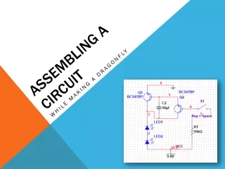
Assembling a Circuit
Learn how to assemble a dragonfly circuit using LEDs, transistors, resistors, and capacitors step-by-step. Understand basic circuit concepts and create your own functional LED dragonfly. Suitable for beginners in electronics.

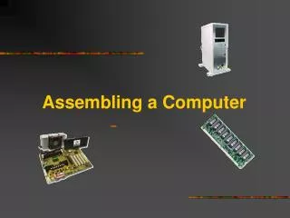
Assembling a Circuit
E N D
Presentation Transcript
Assembling a Circuit While Making A Dragonfly
With... • 2 LEDs • 2 Transistors 1 Resistor 1 Capacitor • 1 9V Battery • 1 Battery Clip • 9 Electric Wire Connectors Pairs • 8 Electrical Wires • 3 Jumper Wires • 4 Zip-ties
Now let’s move into the components…. Let’s start with the basic Concepts of Circuits • Voltage (V) • Is the difference in charge between two points • This comes from the 9V battery supply we are using today • Current (I) • Is the rate of which charge is flowing through a circuit • Resistance (R) • Is a material’s (or multiple materials’) ability to resist the flow of charge Electrical and Electronics Engineers use this formula to createbalanced and stable circuits. Voltage (V) = Current (I) x Resistance (R)
Light Emitting Diodes (LEDs) • LEDs are two-lead components that work in one direction. • This means that one lead is positive (called an anode) while the other is negative (called the cathode). • The negative side is the flat side of the brim. • LEDs emit light, when an appropriate voltage (called a turn on voltage) is applied. • The 2 LEDs will be used as your dragonfly’s eyes!
Transistors • Transistors have three leads and are used to amplify or switch (to turn on and off) electronic signals and electrical power. • The 2 transistors amplify the voltage in your circuit!
Resistors • Resistors are two-lead components, that reduce current flow • Direction is not a concern • The resistor in your circuit keeps your LEDs from burning up!
Last but not least, Capacitors • Capacitors are two-lead components, that store charge (like a tiny battery) • Direction does matter! • In your circuit the capacitor will allow the LEDs to dim off instead of immediately turning off. • A bigger capacitor (than what we are using today) would let the LEDs stay on longer before dimming out
Now let’s Build YOUR DRAGONFLY!!! • Use your connectors to construct your • Dragonfly's right wing • Fix pieces of wire in stubs 4, 6 and 7. (Start counting from where the eyes will be mounted) • Dragonfly's left wing • Fix pieces of wire in stubs 4, 5 and 6
Building YOUR DRAGONFLY • Fix the (2) 3 single connector stubs on the tips of the wires • Bind the loose connectors together with Zip-ties. • Pull the Zip-ties as tightly as possible.
Building YOUR DRAGONFLY • The Left Eye • Fix the LED’s negative-lead into the left side of connector number two. • Let the positive-lead run along the front side of the connectors.
Building YOUR DRAGONFLY • The Right Eye • Fix the other LED’s positive-lead into the right side of the first connector. • Let the negative-lead run along the front side of the connectors. • Connect both eyes across the front side of the Dragonfly's body. • Twist them together carefully with small pliers.
Building YOUR DRAGONFLY • Mount a battery to the lower part of the dragonfly's back end. Use two Zip-ties to fix the battery. • Our body has 1 terminal pair shorter, but no worries the dragonflies will still look cute!
Building YOUR DRAGONFLY • To get the power from the battery to the dragonfly, you need to use a battery clip. • Fix the battery clips red lead into the eighth connector stub, on the right side of the body. • Fix the black lead in the seventh connector stub, on the left side of the body. • Don't connect the battery to the clip yet! *** You will end up frying your parts *** • Connect stubs 2 and 4 on the right side with a piece of jumper wire.
Building YOUR DRAGONFLY • Twist together one lead of a 10k Ohm resistor with a longish piece of jumper wire (with your fingers)!
Building YOUR DRAGONFLY • Fix the wire with the resistor into the first connector-stub, on the left side. • Fix the jumper wires' free end into stub number 8, also on the left side. • The resistor is now fixed with one tip. The other tip sticks out, like a dragonfly's antenna.
Building YOUR DRAGONFLY • Fix the other ending of the wire into connector stub number 5, on the right side of the body. • This is the second antenna. Bend it forward, across the Dragonfly's head.
Building YOUR DRAGONFLY • On the tip of each wing, a transistor is needed. But... be careful! The transistors must be mounted in the right way or your dragonfly won't turn on properly • The left and right wing transistors point the same way! • Let your instructor tell you which way the flat side points. • (one room points up the other points down) • Then connect the three leads into the three connector stubs for both sides.
FINALLY the LEGs • Find 2 free connector stubs connect the electrical wire at the 9th position on the body and attach 2 small connectors (as the feet)
Now its time to Test your Dragonfly(without the capacitor) • When you connect the battery to the battery clip and touch both antennas together, the LEDs should light up!Just like when turning on a light switch. • If not, don't panic! Just unplug the battery and raise your hand so we can troubleshoot it! • First, check the transistors! • Check the LEDs! Did you connect them in the right way to each other and into the connectors? • Check all the wires. Are they fixed into the right connectors? • Check the connections, esp. with the transistors. Sometimes the small leads escape from the screw's pressure.
Now Let’s Add the capacitor…. • But first do you see how the LEDs immediately turned off. • Now let’s unplug the battery and add the capacitor! • The positive side goes on the 5th spot (side with the longer lead) • The negative side goes on the 6th spot (has the grey strip)
Now let’s turn it back on • Connect the battery clip to the battery and touch the two antennas together • The LEDs will light up and when you break the antennas connection by opening the circuit you will see that the LEDs will dim off.