Download
1 / 24
350 likes | 997 Vues
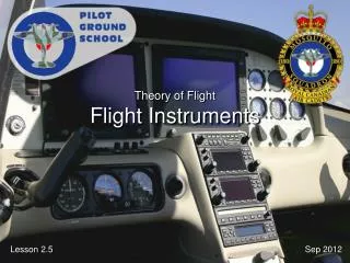
Theory of Flight Flight Instruments. Reference. From the Ground Up Chapter 2.2: Flight Instruments Pages 33 - 44. Introduction. Flight instruments give the pilot all the information they need to properly operate the plane.

E N D
Reference From the Ground Up Chapter 2.2: Flight Instruments Pages 33 - 44
Introduction • Flight instruments give the pilot all the information they need to properly operate the plane. • Pilots need to know what all the instruments do and how they operate.
Outline • Pitot-Static Instruments • Gyroscopic Instruments • Magnetic Compass
Pitot-Static System • Pitot Tube • Measures dynamic and static pressures (AKA pitot pressure) • Positioned clear of slipstream and facing line of flight.
Pitot-Static System • Static Port (AKA Static Vent) • Measures static pressure • Allows instrument cases to be same pressure as outside • Normally on side of aircraft and parallel to airflow
Pitot-Static System Vertical Speed Indicator (VSI) Airspeed Indicator (ASI) Altimeter (Alt) Static Port Pitot Tube
Altimeter (Alt) • Shows height in feet • Measures pressure of outside air (drops with altitude) • Aneroid capsules (like balloons) inside are set to standard pressure. As altitude changes, capsules expand and contract, moving needle on dial.
Altimeter Errors • Pressure Error - Atmospheric pressure changes from place to place • Temperature Error - Pressure changes with temperature • Mountain Effect - Near mountains, gusty winds can drop local pressure
Altitudes • Indicated Altitude – What is read off altimeter when set to current pressure • Pressure Altitude – What is read off altimeter when set to standard pressure (29.92” Hg) • Density Altitude – Pressure altitude corrected for temperature • True Altitude – Exact height above Mean Sea Level (MSL) • Absolute Altitude – Actual height above ground
Airspeed Indicator (ASI) • Shows speed through air (not over ground) • Shows Indicated Airspeed (IAS) in Knots or Miles Per Hour (MPH, older system) • Aneroid capsule connected to pitot pressure. Case connected to static pressure. Aneroid capsule inflates with more airspeed, moving dial clockwise. Static pressure in case corrects for altitude.
Airspeed Errors • Density – Atmospheric density Varies and thus changes accuracy of ASI • Position – Eddies/turbulence created by aircraft disrupt normal airflow into pitot tube or around static port. • Lag - Slowness of mechanical parts due to friction • Icing/Water – Can block pitot tube or static port
Airspeeds • Indicated Airspeed (IAS)– What is read off dial • Calibrated Airspeed (CAS) - IAS corrected for instrument and installation errors • True airspeed (TAS) - CAS corrected for density and temperature (actual speed through the air)
Airspeed Markings Green Arc Normal Range (Lower limit = VS) Red Line Never Exceed Speed (VNE) Yellow Arc Caution Range (Lower limit = VNO) White Arc Flaps Range (Upper Limit = VFE, Lower limit = VSO)
Vertical Speed Indicator • VSI Indicates speed up or down (rate of climb/descent) in feet per minute (FPM) • Static pressure enters aneroid capsule and case. But pressure in case delayed. Capsule registers difference in pressure (as descent or climb) on dial. • Tends to lag. Will only show accurate rate after several seconds
Variometer • Very sensitive VSI used in gliders to find thermals
Gyroscope • Wheel (rotor) spinning fast in universal mounting (gimbal), so axis can point any direction • Gyroscopic Inertia - Tendency of rotating body to maintain it’s plane of motion • Precession – When force applied to point on rotating body, body acts as if force applied 90 degrees in direction of spin
Heading Indicator (HI) • HI(AKA directional gyro) indicates heading without errors associated with compass • Operates on principle of gyroscopic inertia • Drifts off and must be corrected approx every 15 min (set to compass)
Attitude Indicator (AI) • AI (AKA Artificial Horizon) represents horizon as seen by pilot • Used when horizon is obscured by weather • Operates on Gyroscopic Inertia
Turn and Slip Indicator • Needle shows direction and rate of turn • Ball shows slipping or skidding, in turn: • If ball opposite needle = skidding • If ball on same side as needle = slipping • Operates on Gyroscopic Precession
Turn Co-Ordinator (TC) • Replaces Turn and Slip Indicator on newer planes • Similar to turn and slip indicator, but responds to roll and yaw in a turn • Operates on Gyroscopic Precession
Magnetic Compass • Dual magnet system mounted on pivot and able to freely rotate in compass bowl filled with alcohol (lower freezing point and more lubricating than water) • Lubber line is parallel with longitudinal axis, indicates aircraft heading • Only accurate when aircraft flying straight and level at constant airspeed
Next Lesson 4.1 – Air Law Aerodromes From the Ground Up Chapter 4.1: Aerodromes Pages 89 - 98