Download
1 / 23
230 likes | 390 Vues
Section Matériaux EPFL Spring 2010. Practical work on Micro structuration of materials. P. Muralt Janine Conde Alvaro Artieda Evgeny Milyutin Yan Yan Nachiappan Chidambaram. Laboratoire de Céramiques Thin Film & Device group. Outline. Goals Device Characterization.

E N D
Section Matériaux EPFL Spring 2010 Practical work on Micro structuration of materials P. Muralt Janine Conde Alvaro Artieda Evgeny Milyutin Yan Yan Nachiappan Chidambaram Laboratoire de Céramiques Thin Film & Device group
Outline • Goals • Device • Characterization
Objectifs The goal is to learn standard techniques of micro patterning as used in semiconductor and microsystem (MEMS) industry. The major part of the work will be carried out in Centre de Microtechnologie (CMI). We learn there how to behave in clean rooms, and how to use some standard tools. The progress of the work must be recorded on process tracking sheets. At the end, a report covering processing, views of patterned structures, and the characterization of the fabricated infrared emitters must be written.
General remarks • In the PT, a micro hot plate is fabricated and tested as infrared source. Of course there also other applications such as for micro evaporators, catalytic sensors, and micro chemical reactors. • The lecture « Micro and Nanostructuration of Materials» of P. Muralt, Monday 8h to 10h in MXF1, will alternate with the practical work (see calendar p. 19). • This course combines well with the course on thin films given in the autumn semester. Together, these courses and the TP give a complete introduction into microfabrication of materials
Ceramics Laboratory Microfabrication of IR source (hot filament)
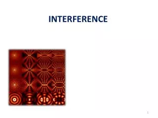
dE dW dF Physical Background: Thermal Radiation Every body possessing a temperature is radiating energy into space. The emitted radiation is called thermal radiation. In principle, its spectrum contains all frequencies n or wavelengths l of electromagnetic waves from 0 to infinity. However, the intensity is not uniformly distributed. The energy distribution is a function of temperature and physical properties of the radiating body. The laws of thermal radiation have been established in experiment and theory by Kirchhoff (1860), Stefan (1887), Boltzmann (1884), Wien (1893) and Planck (1900). The spectral emissivity is E(l ,T) dl dW dF is the energy in the wavelength interval between l and l +dl that is emitted perpendicularly from the area element dF of a body into the space angle element dW . If the body receives a radiation at the same temperature, a fraction A(l ,T) is absorbed, and a fraction R(l ,T)= 1-A(l ,T) is reflected. The dimensionless quantities A and R are called absorptivity and and reflectivity, respectively. The universal relation E(l ,T) dl=A (l ,T) *K (l ,T) dl (Law of Kirchhoff) follows from the second law of thermodynamics. K (l ,T) is an universal function that is independent of materials constants. A body that is absorbing all radiation is called black body: A(l ,T) =1. K (l ,T) is thus the emissivity of a black body. T, A
Black body radiation The black body radiation can be realized by a hollow body from which radiation escapes through a small hole. In practice, a hole that is 4 times as deep as its diameter is sufficient. This trick is sometimes used for pyrometric temperature measurement. The black body radiation was found to follow the law: T (Planck’s law 1900) This formula was first derived to fit experiments. For theoretical justification, Planck had to assume the quantization of light energy (i.e. to introduce the constant h). This equation thus represents the birth of quantum mechanics, even though Planck did not understand energy quantization as a general principle (this was proposed by Einstein on the occasion of the theory for the photoeffect)
Black body radiation The maximum of the radiation is shifted to larger wavelengths when the temperature decreases. The corresponding law is know as Wien’s law T lmax 300 K 8.7 µm 1000 K 2.9 µm 5000 K 580 nm • In micro technology infrared radiation is used for: • infrared imaging - gas spectroscopy • intruder detection - photoacoustic gas sensors Need infrared source
Applications based on IR radiation in micro sensors Intruder alarm: Catching IR radiation 30 m max. Kohli et al. 1997
Gas sensors Hot filament Absorption: + hn Each molecule has its characteristic absorption spectrum Infrared detector Photon absorption leads to rotational and vibrational energy, which is thermalized quickly, leading to a temperature increase dT. Can be micro source The pressure increase can be measured as well: photo-acoustic gas sensor. Standard solution for CO2 detection. If gas is enclosed: dT --> dp=nk*dT
≈ U, I, freq Device of this TP • The heat is created by the current • flowing through the filament • (Joule effect). P = R I2 IR source (hot-filament) • A higher temperature provides a higher • flow of radiated energy. Ir = e·s·A·T4 h
1 • 3 main steps for the microfabrication: • Filament microstructuration • Protection layer (SiO2) • Backside micromachining (membrane) Step 0 - Substrate preparation PVD Platinum 100 nm Wafer: 4” (100 mm), double side polished, 390 µm Thermal SiO2 650 nm LPCVD Si3N4 200 nm Si substrate 390 µm
Step 1 - Filament Photoresist (PR) a) Photolithography Platinum thin film c) Strip PR Remover b) Filament microstructuration Dry etching, STS with Cl2
PVD SiO2 (200 nm) Step 2 - Passivation layer and contact opening b) Photolithography (contacts) a) PVD SiO2 (passivation layer) c) SiO2 wet etching (BHF) d) Strip PR
Step 3 - Backside windows and Si bulk micromachining b) SiN/SiO2 dry etching PR a) Photolithography c) Si bulk micromachining Strip resist !!!! KOH
Additional process within the TP: As example of selective coating: Fabrication of micro grid for micro solid oxide fuel cell By electrochemical deposition
Coaching The TP is based on the competences of the device group of the Ceramics Laboratory (LC). The fabrication of micro devices is to a great deal a team Work. The instructor team Janine Conde Alvaro Artieda Evgeny Milyutin Yan Yan Nachiappan Chidambaram Janine Conde MXD 231, 32944 We also get the support of the CMI staff, particularly by G.-A. Racine
Plan, Monday 8-12h, TP with one group 22-02-2010 Cours - TP intro 08h15, MXF1 1-03-2010 Cours 1 08h15, MXF 1 8-03-2010 TP 1 08h15, MXC-239 (JC, EM, YY, NC) 15-03-2010 Cours 2 08h15, MXF1 22-03-2010 TP 2 08h15, CMI (JC, EM, YY, NC) 29-03-2010Cours 3 08h15, MXF1 5-04-2010Easter break 12-04-2010 TP 3 08h15, CMI (JC, EM, YY, NC) 19-04-2010 Cours 4 08h15, MXF1 26-04-2010 TP 4 08h15, CMI or lab (YY, NC) 03-05-2010 Cours 5 08h15, 10-05-2009 TP 5 08h15, Lab, exp. EM, NC 17-05-2010 Cours 6 08h15, MXF1 24-05-2010 Whitsuntide 31-05-2010 TP 6 10h15, Lab LC (all)
Programme et responsabilités TP1 - Video on clean room - Z6 : Photolitho training (RC8 et MA6 -Mask1: Meandre) → Pt etch (JC, EM, YY, NC) - Z3 : Sputter tool (open and tack off wafers from BAS) - Z2 : Pt etching (STS 1 or 2 wafers by team if enough time) TP2 - SiO2 protection layer: deposition in Spider (JC, EM, YY, NC) (1 wafer if time, at room T° - 200nm) - Photolitho training (Mask 2: Oxide) → SiO2 patterning - SiO2 Wet etch in BHF bath – Strip resin + Tepla - TEM? TP3 - Photolitho automatic (Rite Track 1 and 2 - Mask 3: backside on MA6) (JC, EM, YY, NC) - Dry etching (SiN/SiO2) in Alcatel 601 – PR remover and tepla - Si bulk backside micromachining (in KOH40% - 60°C) TP4 - Electroplating, TEM (YY, NC) TP5 - Characterization (EM, NC) TP6 - Preparation report, check documents (all)
Sécurité et Comportement en salle blanche Safety and behavior in clean rooms
Homework 1 To prepare for second week (TP 1): Describe on one page the steps a photolithographic process using a contact mask with 1:1 writing. (Course, web page du CMI (http://cmi.epfl.ch) :photolitho en mode contacte). What means positive and negative resist? Take as an example the mask aligner MA6 of CMI (web, with picture). Sputter deposition (search on web, or thin film course of past semester) Process tracking sheets / Feuilles de routes Process conditions and results must be written up in the “feuilles de routes” (process tracking sheets) during the the execution of the processes.
Final report • General introduction to the applied processes • Specific issues of the processes run, photos to document results, discussion of quality or problems • Evaluation of device • Phenomena of recrystallization of Pt, measure twice the same filament • Resistivity as a function of temperature • Emissivity evaluated by means of Calibrated IR detector • Thermal time constant • Appendix with “feuilles de routes” (process tracking sheets)