Download
1 / 23
230 likes | 400 Vues
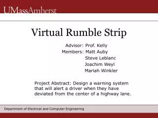
An Onboard Virtual Rumble-Strip Based Operation for Road Departure Warning. During of Project: 18 months July 1, 2010- December 31, 2011 Progress Update presented at the NATSRL Research Advisory Panel Meeting By Jiann-Shiou Yang Department of Electrical and Computer Engineering

E N D
An Onboard Virtual Rumble-Strip Based Operation for Road Departure Warning During of Project: 18 months July 1, 2010- December 31, 2011 Progress Update presented at the NATSRL Research Advisory Panel Meeting By Jiann-Shiou Yang Department of Electrical and Computer Engineering University of Minnesota Duluth
Project Goals/Objectives • The proposed research focuses on developing an onboard electronic virtual rumble-strip based technique for road departure warning (RDW) where the rumble-strip warning threshold is allowed to vary according to the risk of the vehicle departing the road. • Development and implementation of the fuzzy logic-based RDW system requires less sensor information, making it more feasible in a vehicle application.
Project Goals/Objectives (Continued) • We evaluate the current vehicle status and decide if the rumble-strip threshold needs to be adjusted. If no adjustment is needed, the system would act as a standard rumble-strip warning system at the preset threshold level. Just like the road-based rumble strip, the onboard rumble strip would send (sound) a warning signal when the vehicle crosses a specified threshold and the threshold can be widened or tightened.
Expected Benefits • Even though vehicle-based RDW can incur a cost to equip the vehicle, but once installed the RDW will be potentially available for the driver while driving on all roadways. • The onboard electronic implementation of the variable rumble strip for the road departure warning systems allows the rumble-strip threshold to vary according to the risk of the vehicle departing the road. • The system developed will require less sensor information as compared to the TLC approach, making it more feasible in a vehicle application. • “Roadside rumbles cause a grumble”, “Rumble strips unpopular in other Minnesota counties, too” (September 12, 2010 articles, Duluth News Tribune)
A brief Overview of theResearch Methodology Vehicle Lateral Position Estimation and Testing (Real-time feature tracking using homography) The project focuses on using the vehicle’s relative lateral characteristics as input while the vehicle traveling on the road. The decision-making mechanism and operation algorithm will be developed based on the input space information to produce an adjustment to the rumble-strip threshold. The linguistic “IF-THEN” rule-based approach is our focus when developing the operation mechanism. RDW System Development and Implementation (Rule-based fuzzy logic decision making will be developed to provide RDW) Main Tasks: Performance Evaluation
Vehicle Lateral Position Estimation • Since our proposed virtual rumble-strip operation focuses on the development and implementation of a linguistic fuzzy-logic rule-based approach with a hierarchical structure, we don’t actually need a very accurate vehicle’s lateral position information, a rough estimate will be sufficient. The Plane Projective Transform (PPT) technique will provide the lateral characteristics we need.
Initialization (Initial vehicle lateral position, heading angle θo, camrea intrinsic parameters, etc.) Front-view image Homography Top-view image Image comparison and calculation to determine Δθ Update θi+1= θi + Δθ Calculate lateral displacement (relative to its previous lateral position; speed × time (# of frames) × sin (θi+1)+ yi) No Yes Lane markers available?
Vehicle Lateral Position Estimation (Continued) Conversion of front-view images to top-view images via the OpenCV 2 (Open Source Computer Vision) • First alpha version released in 2000 (at the IEEE Conference on Computer Vision and Pattern Recognition); the second major release was in October 2009 • OpenCV was designed for computational efficiency and with a strong focus on real time applications. • One of OpenCV’s goals is to provide a simple-to-use computer vision infrastructure that helps people build fairly sophisticated vision applications quickly.
Vehicle Lateral Position Estimation (Continued) • Vehicle’s heading angle (orientation) update via consecutive top-view images feature selection and tracking • Timeline to complete this task: January 31, 2011
Vehicle Lateral Position Estimation Supplement
Vehicle Lateral Position ( ) Estimation (Continued) • The position of the camera is obtained by the following sequence operations: • Registration of two consecutive images (by accumulating the movement between two consecutive frames) • Conversion to top-view images via the planar projection transform (homography) To obtain the homography between the ground and the image plane at the next frame, the computation of a rotation matrix is required which is based on the vehicle’s speed and the angle of direction. In short, homographies are obtained mainly based on the information of the calibrated camera and the vehicle’s speed. • Feature selection, tracking and threshold checking (between consecutive top-view images obtained from the previous step and compare it with the preset threshold) Basic Approach: Compare successive converted top-view images to determine how far in which direction the vehicle moved relative to the previous frame.
Vehicle Lateral Position ( ) Estimation (Continued) • If the road curves while the vehicle is still moving straight, this will immediately produce a “mismatch” of the present and the previous top-view images (i.e., produce a high SAD value about a preset threshold), and this “beyond the threshold mismatch” will immediately trigger a warning signal (vibrations, sound) to the driver. The detection of the variations of the SAD value (whether above the threshold or not) between consecutive top-view images (matching) can deal with the road curvature issue.
Vehicle Lateral Position ( ) Estimation (Continued) • The PPT approach calculates the vehicle’s lateral displacement by accumulating successive movements of the camera. Then, it determines the vehicle’s current position relative to its “initial” position. How to determine its “initial” position? • Approach # 1 – The driver starts driving the vehicle to the lane he is heading. Once the vehicle moves close to the center of the lane (i.e., its “initial” position), the driver then activates the RDW system and leave it on while traveling on the roadway. • Approach # 2 – In this approach, the “initial” position will be determined by any road edge detection method (several techniques are available). However, this information is only needed once (to locate the vehicle’s initial position). Then, the driver activates the RDW system (without the initial driver’s visual maneuvering close to the center of the lane) and leave it on while traveling on the roadway.
Vehicle Lateral Speed • The assumption of small heading angle and constant forward speed are justifiable for highway driving conditions. u: forward speed For small : average forward speed and are sufficient to describe the vehicle’s relative lateral characteristics Thus, for normal highway driving, the vehicle state can be adequately specified by knowledge of relative lateral velocity ( ), and the measurement of the relative lateral position ( )
Rule-Based Fuzzy Logic Decision Making Supplement
Variable Rumble Strip (VRS) Approach (Continued) Fuzzy-Logic Decision Making The decision-making part of the VRS system is to take and inputs and produce an adjustment to the rumble-strip threshold IF-THEN rules: Example: If ( is far) and ( is small) then (∆VRS = 0) The rule generation represent heuristics of how the VRS is to behaved. The rule base, simply a set of linguistic descriptions, is complete in the sense that, at any point in the input space, at least one of the rules developed is active.
Fuzzy-Logic Structure for Decision Making The rule-based approach will be implemented using a fuzzy-logic structure. The implementation includes input range, I/O membership function formation, Mamdani-style inferencing, and aggregation methods. Centroid defuzzification will be performed on the aggregated outputs. • Fuzzy rule base and rule generation • Input/output membership function formation • Fuzzy VRS system output
Performance Evaluation via Driving Simulation Experiments • Investigation of the performance of any RDW system still requires access to realistic data on road departures. However, due to the safety concern of directly putting drivers at risk to collect road departure events, driving simulator experiment seems to be a better and more realistic way to conduct such a study. • Driving simulator experiments also have flexibility to safely generate road departure events, as opposed to onboard system using computer-vision techniques (weather conditions such as snow, fog, and glare may inhibit widespread functionality and adoption). • Performance evaluation, in terms of hits, misses and false alarms, will be conducted via simulator experiments.
Performance Evaluation via Driving Simulation Experiments (Continued) • Driving simulator UC-win/Road, available in the NATSRL lab (207 Engineering Building), will be used to conduct experiments. • Implementation of a “built-in” warning mechanism to the system (when the vehicle crosses a specified threshold) will be developed. The virtual rumble-strip based operation will issue a warning signal in the form of ♦ Sound (alarm) ♦ Vibrating seat Integration and interfacing of the hardware and software to implement the above two modes will also be developed.
Concluding Remarks • Shoulder rumble strips have proven to be very effective for warning drivers that they are about to drive off the road. However, rumble strips require an infrastructure and do not exist on a majority of roadways. • Even though vehicle-based RDW can incur a cost to equip the vehicle, but once installed the RDW will be potentially available for the driver while driving on all roadways. • The proposed research will investigate and develop an onboard electronic implementation of a virtual rumble-strip based road departure warning system, where the warning threshold is allowed to vary according to the risk of the vehicle departing the road.
Concluding Remarks (Continued) • Our proposed system will require less sensor information as compared to the TLC approach, making it more feasible in a vehicle application. • The RDW system to be developed will capitalize on the simplicity of the fixed threshold rumble strip and enhance performance by allowing the effective threshold to be closer to the road edge without incurring an increase in false warnings.