Download
1 / 28
280 likes | 464 Vues
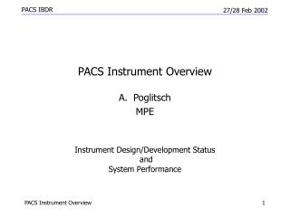
Instrument Design/Development Status and System Performance. PACS Instrument Overview Poglitsch MPE. Focal Plane Footprint. 32 x 16 pixels 6.4” x 6.4”. 64 x 32 pixels 3.2” x 3.2”. Instrument Concept. Imaging photometry

E N D
Instrument Design/Development Status andSystem Performance • PACS Instrument Overview • Poglitsch • MPE PACS Instrument Overview
Focal Plane Footprint 32 x 16 pixels 6.4” x 6.4” 64 x 32 pixels 3.2” x 3.2” Instrument Concept • Imaging photometry • two bands simultaneously (60-85 or 85-130 µm and 130-210 µm) with dichroic beam splitter • two filled bolometer arrays (32x16 and 64x32 pixels, full beam sampling) • point source detection limit ~3 mJy (5s, 1h) • Integral field line spectroscopy • range 57 - 210 µm with 5x5 pixels, image slicer, and long-slit grating spectrograph (R ~ 1500) • two 16x25 Ge:Ga photoconductor arrays (stressed/unstressed) • point source detection limit 2…8 x10-18 W/m2 (5s, 1h) PACS Instrument Overview
Observing Modes • Combinations of instrument modes and satellite pointing modes • Instrument modes: • dual-band photometry • single-band photometry • line spectroscopy • observation of individual lines • range spectroscopy • observation of extended wavelength ranges • Pointing modes: • stare/raster/line scan • with/without nodding PACS Instrument Overview
FPU Cold FocalPlaneUnit DEC/MEC 1 BlueGe:GaArray &CRE MPE/ANTEC/IMEC MEC I/F-Module BOL/COOL BOL/BAU BlueBolArray &Read-out CEA BlueBol BAU BOL 1 Module DSP Module RedBolArray &Read-out CEA RedBol BAU BOL 2 Module BlueDEC Module CEA RedGe:GaArray &CRE MPE/ANTEC/IMEC Cooler Control Base/PSU SPU nominal DPU nominal CEA CSL-Liege IAC-Tenerife/TU-Wien 0.3K Cooler CEA DEC/MEC 2 DPU redundant SPU redundant MEC I/F-Module Redundant Grating Assy CSL-Liege IFSI-ROME IAC-Tenerife/TU-Wien DSP Module Redundant Chopper Assy MPIA 2FilterWheels KT RedDEC Module Base/PSU Redundant 2BlackBodies KT Warm Interconnecting Harness KT/MPE CSL-Liege Instrument Overview and Subsystem Responsibilities PACS Instrument Overview
DPU • Single point of communication with satellite • TC/TM • reception and execution or distribution of commands • transfer of science and HK data • autonomy functions PACS Instrument Overview
SPU • Data compression • lossy part (average / fit) • lossless part (redundancy removal) • Must reduceraw data rate from up to3.6 Mbit/s to ~120 kbit/s PACS Instrument Overview
DECMEC • Photoconductor operation and readout • CRE supply and timing/control • detector bias • signal acquisition • FPU mechanisms control/ synchronization • chopper • filter wheels • grating • BOLC data acquisition and control • Communication with SPU and DPU PACS Instrument Overview
BOLA / BOLC BOLA • 160-channel JFET buffer at ~100 K BOLC • Acquisition of signals from 160 multiplexers in bolometer arrays • Sequencer for bolometer operation / readout • Control of 300 mK cooler • Transfer of digitized data to DECMEC PACS Instrument Overview
FPU Cold FocalPlaneUnit Photometer Optics BlueGe:GaArray &CRE MPE/ANTEC/IMEC Filter Wheel I Slicer Optics Blue Bolometer BlueBolArray &Read-out CEA 0.3 K Cooler RedBolArray &Read-out CEA Grating Red Bolometer Grating Drive RedGe:GaArray &CRE MPE/ANTEC/IMEC Encoder sGeGaDetector Red Spectrometer 0.3K Cooler CEA Spectrometer Optics Chopper Grating Assy CSL-Liege Calibrator I and II Filter Wheel II Chopper Assy MPIA Calibrator Optics GeGa Detector Blue Spectrometer 2 FilterWheels KT 2 Calibrators KT Entrance Optics KT/MPE FPU/Optics PACS Instrument Overview
Design/Development Status of Technically Critical Components • Optics • FPU/Structure • Photoconductors, CRE • Bolometers • Chopper • Grating assembly • Warm electronics PACS Instrument Overview
Optics • Design of FPU optics complete, manufacturing of mirror blanks started • Alignment plan exists; tolerancing partly done • Analyses (geometrical-optical, diffraction) done end-to-end for selected cases; coverage of parameter space (wavelength, chopper angle) to be improved in context of instrument calibration • Baffle design of FPU nearly finished; straylight analysis difficult • Calibration sources conceptual design achieved • Details from N. Geis PACS Instrument Overview
FPU Status • Detailed design of FPU structure in final phase.Structural problems solved.First part (“top optics”) in manufacturing. • Delay for manufacturing from some interface problems and from late input • bolometer unit mounting interface • electrical distribution board design • detector array cable harness • filter mounts • Details from J. Schubert and D. Kampf PACS Instrument Overview
Photoconductor Arrays • Environmental testing successful • Performance tests on both high and low-stress modules with TIA: QE looks ok (high-stress: >30%) • Design Changes • short-circuit “immunity” implemented in FM design • Manufacturing Status • QM completed – but FEE integration outstanding • FM in production • Problems • “pigtail” harness late and hard to fit in FPU • late readiness of FEEs • Details from H. Richter and D. Rosenthal PACS Instrument Overview
Cryogenic Read-Out Electronics • CREs have undergone complete redesign over the last two years • Progress with new design from both, optimization of transistor geometry and of circuit design • CQM run ‘032001’ • design/layout improvement and local optimization of input stage • successfully tested by IMEC and by CSL, working at MPE • will be used for detector module tests at LENS • CQM run ‘102001’ • essentially integrator type _024 (as 032001) • evolutionary combination of additional features (4 Cint, increased dynamic range) • for integration into QM detector modules, dice delivery 11/2001 • Details from C. van Hoof PACS Instrument Overview
CRE032001 Performance • Linearity : <3% non-linearity over >2V • Cross talk between channels: <1% full range • Noise, linearity, cross talk~ meet requirements • Tests of CREs with detectors still ahead (early ’02) PACS Instrument Overview 16
Bolometer Arrays • Two complete “blue” arrays mounted in cryostat at LETI for optical characterization • Red arrays being assembled • Cold multiplexer/buffer noise (differential mode)< 1 µV/Hz1/2 • Detection efficiency 80%(calculated) across PACSspectral bands • Good tolerance to uncertaintyin background level shown bymodeling • Details from L. Rodriguez PACS Instrument Overview
3He Sorption Cooler • 300 mK cooler development on track, good margin for 46h operation • Details from L. Duband PACS Instrument Overview
Chopper • Status QM • Manufacturing at MPIA started mid Oct 2001 • Qualification tests started January 2002 • Delivery to MPIA/MPE/KT planned for March 2002, but delayed due to pigtail delivery • Problems • Damage of flex pivots in lifetime model operation • Details from R. Hofferbert PACS Instrument Overview
Grating • Diffraction Grating Sample received from Zumtobel GmbH (A), under evaluation Zeiss for FM manufacture as backup • Actuator ordered from TU Berlin after successful performance test at 4K • Position Sensor ordered from FARRAND after successful breadboard test of sensor at 4K • Bearings coatings and preload control under evaluation • Launch-lock prototype under fabrication • More information from E. Renotte PACS Instrument Overview
Warm Electronics Development • BOLA • Mechanical design updated • Box thermal behavior modeling in progress • JFET modeling for effect of temperature on performance in progress • BOLC • Mechanical design BOLC updated (2 stacked boxes) • Analogue board prototype ready for performance test • Bolometer bias board (QM1) ready for design • “300mK” temperature control prototype designed • FPGA implementation of IEEE1355 under test at CSL • Most digital functions designed, except bolometer sequencer PACS Instrument Overview
CRE 03/01 @ 4K Warm Electronics Development • DEC/MEC • DEC/MEC AVM Status • DSP and DEC simulator available / development on schedule • DEC/MEC EM Status • design and procurement ongoing, but validation with representative hardware pending on mechanism simulators availability from partners • DEC/MEC On-board Software Status • sequencer complete • communication 70% tested • mechanism control low-level S/W ~ 0% • MEC-to-DPU simulator completed: Virtuoso + OBS emulated on a PC • Successful operation of CRE with DEC prototype • low noise + good linearity PACS Instrument Overview
Instrument Performance • Instrument Requirements • Photometer • Spectrometer • Instrument Model • Optical performance • Sensitivity budget • optical transmission • background • detector performance PACS Instrument Overview
Photometer Performance Requirements • Image quality • blur: telescope limited • distortion: ±1 pixel; alignment: <1/3 pixel • Sensitivity (point source detection) • requirement: 5 mJy (5s), 1h of integration • goal: 3 mJy (5s), 1h of integration • Dynamic range • detection from 3 mJy to >1000 Jy (goal: 3000 Jy) • contrast of up to 1:500 in one field • Post-detection bandwidth • requirement: 0.5 - 5 Hz • goal: 0.05 - 5 Hz PACS Instrument Overview
Spectrometer Performance Requirements • Image quality • blur: telescope limited • distortion: ±1 pixel; alignment: <1/4 pixel • Sensitivity (point source detection) • requirement: 3x10-18 W/Hz1/2 (5s), 1h of integration • goal: 2x10-18 W/Hz1/2 (5s), 1h of integration • Dynamic range • detection from ~1x10-18 W to >10-13 W • contrast of up to 1:100 in one field • Post-detection bandwidth • requirement: 5 Hz • goal: 10 Hz PACS Instrument Overview
Optical Performance • Optical design fulfills requirements regarding • field of view • spatial sampling • distortion • geometrical spot sizes (Strehl ratio) • alignment • internal calibration capability • chopping • spectral coverage and resolution • transmission / diffraction losses • Details from N. Geis PACS Instrument Overview
Parameters of PACS Instrument Model(Present Best Estimate) (a) Values for the photometry modes from 60-85 or 85-130 µm / 130-210 µm, respectively. (b) The formal transmission of >1 takes into account the acceptance solid angle of the photoconductor light cones / bolometer baffles which differs from the beam solid angle. PACS Instrument Overview
Background, NEP, Spectroscopic and Photometric Sensitivity assumed detector QEs: 30% (spectroscopy); 80% (photometry) assumed detector NEPs: 5x10-18 W/Hz1/2 (spectroscopy); 10-16 W/Hz1/2 (photometry) • Performance requirements (or even goals) can be met PACS Instrument Overview