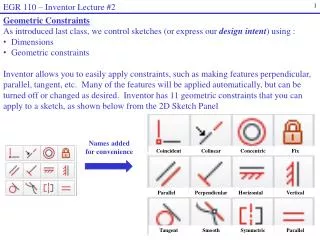
Quadratic Equations in Engineering: Methods, Examples, and Applications
90 likes | 111 Vues
This chapter explores quadratic equations in engineering, including graphical interpretation, solving for specific values, and practical applications. The concepts are illustrated with examples in electrical circuits and resistor networks.

Quadratic Equations in Engineering: Methods, Examples, and Applications
E N D
Presentation Transcript
EGR 1101 Unit 2 Quadratic Equations in Engineering (Chapter 2 of Rattan/Klingbeil text)
Mathematical Review • In linear equations, which we studied last time, the two variables (x and y) are both raised to the first power: • In a quadratic equation, the dependent variable is raised to the first power and the independent variable is raised to the second power. For example:
Graphical Interpretation • The graph of a quadratic equation is a parabola. In MATLAB: > fplot('2*x^2 + 3*x + 10', [-10, 10])
Two Common Questions Involving Quadratic Equations • Given a quadratic equation, find the value of y for a particular value of x. (Easy!) • Given a quadratic equation, find the value of x for a particular value of y. (Harder!)
Three Methods • We’ll study three ways to answer the second type of question: • Factoring • Quadratic formula • Completing the square
Today’s Examples • Height of a projectile • Power and current in a circuit • Resistors in parallel
Some Symbols Used in Electrical Drawings • Resistor: • Voltage Source: • Lamp (light bulb): • Circuit containing thesethree components:
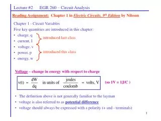
Three Basic Electrical Laws • Kirchhoff’s Voltage Law (KVL): Around any closed loop in a circuit, the sum of the voltage rises is equal to the sum of the voltage drops. • Ohm’s Law: For a resistor, voltage equals current times resistance: V = IR • Power Law: For any component, power equals current times voltage: P = IV
Resistors in Series or Parallel • If two resistors are connected in series (end-to-end), total resistance is the sum of the two resistances: • If two resistors are connected in parallel (connected at both ends), total resistance is given by the product-over-sum rule: