Download
1 / 92
920 likes | 1.26k Vues
LAN and WAN Standards. Hasan Cam Computer Engineering Department King Fahd University of Petroleum & Minerals cam@ccse.kfupm.edu.sa. Computer Networks, February 19 - 23, 2000. Network Standards. Standards allow different computers to communicate

E N D
LAN and WAN Standards Hasan Cam Computer Engineering Department King Fahd University of Petroleum & Minerals cam@ccse.kfupm.edu.sa Computer Networks, February 19 - 23, 2000
Network Standards • Standards • allow different computers to communicate • increase the market for products adhering to the standard, resulting in mass production and cheaper prices • Standards fall into two categories: • De facto (Latin for “from the fact”): those standards that have just happened, without any formal plan (e.g., IBM PC, Unix) • De jure (Latin for “by law”): formal, legal standards adopted by some authorization body
Most Important Standards Organizations • ITU-T: International Telecommunication Union (a United Nations specialized agency, was created on March 1, 1993) • ISO: International Organization for Standardization (an international voluntary, nontreaty organization, founded in 1946) • IETF: Internet Engineering Task Force (responsible for publishing RFCs (Requests For Comments)) • IEEE: Institute of Electrical and Electronic Engineers (ATM Forum: This organization is not a standard organization. After ITU defined the ATM concept in Nov 1990, ATM Forum was initiated in October 1991 to accelerate the deployment of ATM products and services. ATM Forum develops implementation agreements and publishes them as “specifications” on its web site: www.atmforum.com)
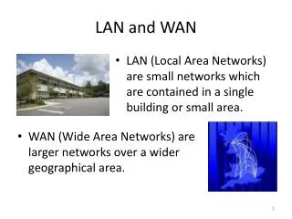
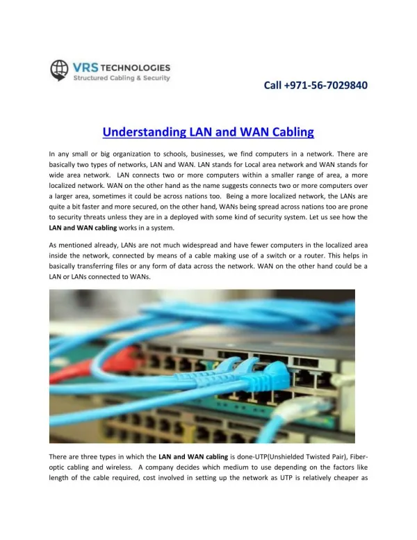
Terminology • Networks are classified on the basis of geographic span. • Local Area Networks (LANs) • Metropolitan Area Networks (MANs) • Wide Area Networks (WANs) • The difference in geographical extent between WANs and LANs account for significant differences in their respective design issues.
Terminology(cont.) • LANs have generally three characteristic features: • A diameter of no more than few kilometers. • A total data rate of at least several Mega bits per second. • Complete ownership by a single organization.
LANs LANs are designed around a high speed low noise connecting link. They operate quite differently from WANs:
MAC (Medium Access Control) Standards • Polling • ALOHA Protocols • CSMA (Carrier Sense Multiple Access) Protocols • CSMA/CD, MAC protocols of Ethernet, Token Bus, Token Ring, FDDI, 100VG-AnyLAN • Wavelength Division Multiple Access Protocols • Wireless LAN Protocols
Communication Protocols • A communication protocol is the set of rules that determines how and when stations are allowed to transmit or receive data, how the data is formatted, and how error checking is performed, etc. • A MAC (Media Access Control) protocol is a set of rules to control access to a shared communication medium among various users. • One station transmit at a time
Three Main Categories • Multiple access schemes can be classified into three main categories: • Fixed Assignment such as • FDMA (Frequency Division Multiple Access) • TDMA (TDMA Division Multiple Access) • Random Assignment such as CSMA, CSMA/CD • Demand Assignment
Poll and Select • Primary (supervisor) station asks each secondary station in a sequence if it has data to send (this process is polling) • A secondary station can send only if the primary station permits. • This method may be used in a star network. • Having backup supervisor for the supervisor malfunctions • Polling list can be modified in case of higher priority stations; Example: 1,2,3,4,5,1,6,7,8,1,2,3,4,5,1,6,7,8,1, ….
ALOHA Protocols • developed for packet radio networks in 1970 • radio encompasses all frequency bands between 30 kHz and 300 GHz • PURE ALOHA • Whenever a station has a frame to send, it does so. Then, station listens for a round-trip propagation time; if no ack, then retransmits. • collision occurs if two frames interfere each other • the number of collisions rise rapidly with increased load.
PURE ALOHA (cont) • maximum utilization of the channel is 18 %. • S = G e • S: Throughput of network • S: (successful load) / (capacity of channel) • G: The total rate of data presented to network • (offered load) • G= S+(number of retransmitted packets per unit time) • vulnerable period = 2 X (frame time) -2G
Slotted ALOHA • vulnerable period = frame time • S = G e • Maximum throughput = 37% -G
CSMA (Carrier Sense Multiple Access) Protocol • A station wishing to transmit first listens to the medium if another transmission is in progress (carrier sense). • If the medium is in use, station waits • if the medium is idle, station may transmit • Collisions can occur only when more than one user begins transmitting within the period of propagation delay.
CSMA (cont) • 1-persistent CSMA • if the medium is idle, transmit. • if the medium is busy, continue to listen until the channel is sensed idle; then transmit immediately. • Nonpersistent CSMA • if the medium is busy, station waits a random amount of time • p-persistent CSMA • if medium is idle, station transmits with a probability p.
CSMA/CD(CSMA with Collision Detection) • Drawback of CSMA: when two frames collide, the medium remains unusable for the duration of transmission of both damaged frames. • CSMA/CD: • 1. if the medium is idle, transmit; otherwise, go to step 2. • 2. if the medium is busy, continue to listen until the channel is idle, then transmit. • 3. if a collision is detected during transmission, transmit a brief jamming signal • 4. after transmitting a jamming signal, wait a random amount of time, then attempt to transmit.
CSMA/CD (cont) • Collisions occur only when more than one user begins transmitting within the period of propagation delay. Frame Frame Frame Frame • To detect collision, the station’s hardware must listen to the cable while it is transmitting. If what it reads back is different from what it is putting out, it knows a collision is occurring.
CSMA/CD (cont) • The IEEE 802.3 standard is for a 1-persistent CSMA/CD LAN. • Ethernet uses 1-persistent CSMA/CD • when a station wants to transmit, it listens to the cable. If the cable is busy, the station waits until it goes idle; otherwise it transmits immediately. • when collision occurs, all colliding stations terminate their transmission, wait a random time, and repeat the whole process again • The binary exponential backoff algorithm is used. • 10BASE5, 10BASE2, 10BASET, 10BASEF, 10BROAD36 <data rate in Mbps><signaling method><maximum segment length in hundreds of meters>
FAST ETHERNET • a low-cost, Ethernet compatible LAN operating at 100 Mbps • 100BASE-T options use the IEEE 802.3 MAC protocol and frame format • 100BASE-X options use the physical medium specifications originally defined for FDDI. • All of the 100BASE-X schemes use two physical links between nodes: one for transmission and one for reception. • 100BASE-TX make use of shielded twisted pair (STP) or high-quality unshielded twisted pair (UTP).
Token Bus (IEEE 802.4) • Disadvantages of IEEE 802.3 CSMA/CD: • a station may wait arbitrarily long to send a frame due to its probabilistic nature. • frames do not have priorities • Physically, the token bus is a linear cable onto which stations are attached. Logically, stations are organized into a ring. • A special control frame called token is transmitted from one station to the next, with each station knowing the address of the station to its ``left’’ and ``right’’. • Token bus defines four priority classes: 0, 2, 4, and 6 for traffic, with 0 the lowest and 6 the highest.
TOKEN RING • IEEE 802.5 Medium Access Protocol • The token ring technique is based on the use of a small frame, called a token that circulates. • A station wishing to transmit must wait until it detects a token passing by. • It then seizes the token by changing one bit in the token which transforms it from a token into a start-of-frame sequence for a data frame. • The station then appends and transmits the remainder of the fields needed to construct a data frame.
TOKEN RING (cont) • The transmitting station will insert a new token on the ring when both of the following conditions have been met: • The station has completed transmission of its frame. • The leading edge of the transmitted frame has returned (after a complete circulation of the ring) to the station. (This condition ensures that only one data frame at a time may be on the ring, thereby simplifying error-recovery procedures).
TOKEN RING (cont) • Once the new token has been inserted on the ring, the next station downstream with data to send will be able to seize the token and transmit. • Note that under lightly loaded conditions, there is some inefficiency with token ring because a station must wait for the token to come around before transmitting. • The principal disadvantage of token ring is the requirement for token maintenance. • Loss of token prevents further utilization of the ring. • One station must be selected as a monitor.
Token Ring Priority • The 802.5 standard includes a specification for an optional priority mechanism. Eight levels of priority are supported by providing two 3-bit fields in each data frame and token: a priority field and a reservation field. P(f): priority of frame P(s): service priority; priority of current token R(s): reservation value in current token • A station wishing to transmit must wait for a token with P(s) <= P(f). • While waiting, a station may reserve a future token at its priority level P(f). • Early token release option is added to the IEEE 802.5 for more efficient ring utilization.
FDDI • The FDDI standard specifies a ring topology operating at 100 Mbps. • Optical fiber or twisted pair are used for medium. • Optical fiber uses4B/5B NRZI encoding. Maximum length between repeaters is 2 km. Maximum number of repeaters is 100. • Two twisted pair media are specified: 100-ohm Category 5 unshielded twisted pair and 150-ohm shielded twisted pair. Maximum length between repeaters is 100m . Maximum number of repeaters is 100.
100VG-AnyLAN • is intended to be a 100 Mbps extension to the 10 Mbps Ethernet and to support IEEE 802.3 frame types. • uses a MAC scheme known as demand priority;it has been standardized under IEEE 802.12. • Its MAC algorithm is a round-robin scheme with two priority levels. • Single-Hub Network • When a station wishes to transmit a frame, it first issues a request to the central hub and then awaits permission from the hub to transmit. • A station must designate each request as normal-priority or high-priority.
100VG-AnyLAN (contd.) • The central hub continually scans all of its ports for a request in round-robin fashion. • The central hub maintains two pointers: a high-priority pointer and a normal-priority pointer. • If at any time there are no pending high-priority requests, the hub will grant any normal-priority requests that it encounters.
100 VG-AnyLAN (contd.) • Hierarchical Network • All of the end-system ports on all hubs are treated as a single set of ports for purposes of round-robin. • Port ordering is done preorder traversal: • Visit the root • Traverse the subtrees from left to right.
100VG-AnyLAN (contd.) • Hierarchical topology • There is a single root Hub (at level 1) • A level 1 Hub may have one or more subordinate level 2 hubs • A level 2 hub can have one or many subordinate level 3 hubs, and so on, to an arbitrary depth • Hub is responsible for converting between 802.3 and 802.5 frame formats if necessary
Example 100VG-AnyLAN Configuration 100VG-AnyLAN Hub 100/10 Ethernet 100VG-AnyLAN Hub Bridge 100VG-AnyLAN Hub Ethernet LAN
MAC of 100VG-AnyLAN(Single hub network) • The MAC algorithm for 802.12 is a round-robin scheme with two priority levels • A station wishing to transmit • it first issues a request to the central hub • it then awaits permission from the hub to transmit • A station must designate each request as normal priority or high priority
Single hub LAN (contd.) • The central hub continually scans all of its ports for request in round-robin fashion • The hub maintains two pointers • a high priority pointer and • a low priority pointer • During one cycle, the hub grants each high priority request in the order encountered • When there are no pending high priority requests, the hub grants normal priority requests in the order encountered
Example Frame Sequence in a Single-Repeater Network 2 7 1 1 9 2 4 3 4 3 5 5 6 6 7 8 8 Ports High priority frame High priority request Normal priority request Normal priority frame
100VG-AnyLAN Priority Scheme Request from port k placed in position k n 1 . 2 . 3 . High priority pointer REQ-H 4 Transmit Frame C 5 B 6 A 7 9 8 8 Time-out High-priority queue empty Request from port k placed in position k . n 1 2 . 3 Normal priority pointer . REQ-N 4 C 5 B 6 A 7 9 8 If a request remains in the normal priority buffer for too long (default=500 ms), it is moved to the corresponding position in the high-priority buffer.
Hierarchical LAN • The set of all hubs are treated logically as one single hub • The port order is generated by performing a pre-order traversal of the tree (depth-first) • Visit the root • traverse the subtrees from left to right • Each hub is running its own round-robin algorithm to service end-systems directly attached to it.
Port Ordering in a Two-Level IEEE 802.12 Network Level 1 “Root” Repeater R 1 2 3 4 5 6 7 1-7 1-6 1-1 1-2 B A 1-4 1 2 k 1 2 k Level 2 Repeater Level 2 Repeater 3-1 5-1 5-2 3-k 5-n
IEEE 802.3 CSMA/CDLabeling Terminology IEEE 802.3 CSMA/CD 100BASE-X 100BASE-TX 100BASE-FX 100BASE-T4 Two Category 5 UTP Two STP Two Optical Fiber Four Category 3 or Category 5 UTP
100 BASE-T • Provides a low cost Ethernet compatible LAN operating at 100 Mbps. • All of the 100 BASE-T options use the IEEE 802.3 MAC protocol and frame format • All of the 100 BASE-X schemes use two physical links between nodes, one for transmission and one for reception • Provides a low cost Ethernet compatible LAN operating at 100 Mbps.
100 BASE-T • All of the 100 BASE-T options use the IEEE 802.3 MAC protocol and frame format • All of the 100 BASE-X schemes use two physical links between nodes, one for transmission and one for reception
100 BASE-T (contd.) • 100 BASE T4 can use • low cost option of CAT 3 voice-grade UTP • higher quality CAT 5 UTP • 100 BASE T4 uses 4 TP lines between nodes, with data transmission making use of 3 pairs in one direction at a time. • Typically, any of the 100BASE-X options require the installation of new cable.
IEEE 802.3 100BASE-T Physical Layer Medium Alternatives _________________________________________________________________ 100BASE-TX 100BASE-FX 100BASE-T4 _________________________________________________________________ Transmission Two pair Two pair Two optical fibers Four pair, cat medium STP cat 5 UTP 3,4 or 5 UTP Signaling 4B5B,NRZI 4B5B, NRZI 4B5B, NRZI 8B6T, NRZ technique Data rate 100 Mbps 100 Mbps 100 Mbps 100 Mbps Max. Segment 100 m 100 m 100 m 100 m length Network 200 m 200 m 400 m 200 m Span _________________________________________________________________
100 BASE-X • For all transmission media specified under 100BASE-X, a unidirectional data rate of 100 Mbps is achieved transmitting over a single link • An efficient and effective encoding scheme is used: 4B/5B-NRZ-I, originally defined for FDDI.
4B/5B-NRZI • Encoding is done 4 bits at a time • Each 4 bits of data are encoded into a symbol of 5 code bits • A set of 5 code bits is a code group • Efficiency: 80% • Each code group is treated as a binary value and encoded using nonreturn to zero inverted (NRZI)
4B/5B-NRZI (contd.) • 1 -> transition at beginning of bit interval • 0 -> no transition • There are no other transitions • For adequate synchronization: no more than 3 zeros in a row are allowed across one or more code groups • Code groups not used for data are either invalid or used as control symbols
4B/5B Code Groups _________________________________________________________________ Data input Code Group NRZI Pattern Interpretation _________________________________________________________________ 0000 11110 Data 0 Data 1 0001 01001 0010 10100 Data 2 0011 10101 Data 3 0100 01010 Data 4 0101 01011 Data 5 0110 01110 Data 6 0111 01111 Data 7
4B/5B Code Groups (Contd.) _________________________________________________________________ Data input Code Group NRZI Pattern Interpretation _________________________________________________________________ 1000 10010 Data 8 Data 9 1001 10011 1010 10110 Data A 1011 10111 Data B 1100 11010 Data C 1101 11011 Data D 1110 11100 Data E 1111 11101 Data F
4B/5B Code Groups (Contd.) _________________________________________________________________ Data input Code Group NRZI Pattern Interpretation _________________________________________________________________ Idle 11111 Start of Stream part 1 11000 10001 Start of Stream part 2 End of Stream part 1 01101 End of Stream part 2 00111 00100 Transmit Error Other Invalid codes
4B/5B code groups (contd.) • Idle code group • transmitted between data transmission sequences • consists of constant flow of binary 1’s • this fill pattern establishes and maintains synchronization • also indicates that the medium is idle
4B/5B Code groups (contd.) • Start-of-stream delimiter • used to delineate the starting boundary of a data transmission sequence • consists of two different code groups (part 1 and part 2) • End-of-stream delimiter • used to terminate normal data transmission sequences (2 different code groups)
100 BASE-TX • The 4B/5B signal is subject to further encoding as follows • NRZI-to-NRZ conversion • Scrambling: the bit stream is scrambled to produce a more uniform spectrum distribution for the next stage • Encoder: the scrambled bit stream is encoded using MLT-3 • Driver: the resulting signal is transmitted