Instruction encoding
Instruction encoding. We’ve already seen some important aspects of processor design. A datapath contains an ALU, registers and memory. Programmers and compilers use instruction sets to issue commands.

Instruction encoding
E N D
Presentation Transcript
Instruction encoding • We’ve already seen some important aspects of processor design. • A datapath contains an ALU, registers and memory. • Programmers and compilers use instruction sets to issue commands. • Now let’s complete our processor with a control unit that converts assembly language instructions into datapath signals. • Today we’ll see how control units fit into the big picture, and how assembly instructions can be represented in a binary format. • On Wednesday we’ll show all of the implementation details for our sample datapath and assembly language. Instruction encoding
D data WR Write DA D address Register File AA A address B address BA A data B data Constant RAM MB ADRS DATA OUT S D1 D0 Q +5V CS MW WR A B FS FS V ALU C N Z D0 F Q D1 S MD Review: Datapath • Recall that our ALU has direct access only to the register file. • RAM contents must be copied to the registers before they can be used as ALU operands. • Similarly, ALU results must go through the registers before they can be stored into memory. • We rely on data movement instructions to transfer data between the RAM and the register file. Instruction encoding
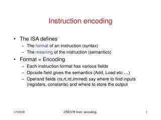
Block diagram of a processor • The control unit connects programs with the datapath. • It converts program instructions into control words for the datapath, including signals WR, DA, AA, BA, MB, FS, MW, MD. • It executes program instructions in the correct sequence. • It generates the “constant” input for the datapath. • The datapath also sends information back to the control unit. For instance, the ALU status bits V, C, N, Z can be inspected by branch instructions to alter a program’s control flow. Program Control signals Control Unit Datapath Status signals Instruction encoding
A specific instruction set • The first thing we must do is agree upon an instruction set. • For our example CPU let’s stick with the three-address, register-to-register instruction set architecture introduced in the last lecture. • Data manipulation instructions have one destination and up to two sources, which must be either registers or constants. • We include dedicated load and store instructions to transfer data to and from memory. • Next week, we’ll learn about different kinds of instruction sets. Instruction encoding
From assembly to machine language • Next, we must define a machine language, or a binary representation of the assembly instructions that our processor supports. • Our CPU includes three types of instructions, which have different operands and will need different representations. • Register format instructions require two source registers. • Immediate format instructions have one source register and one constant operand. • Jump and branch format instructions need one source register and one constant address. • Even though there are three different instruction formats, it is best to make their binary representations as similar as possible. • This will make the control unit hardware simpler. • We’ll start by making all of our instructions 16 bits long. Instruction encoding
15 9 8 6 5 3 2 0 Register format • An example register-format instruction: ADD R1, R2, R3 • Our binary representation for these instructions will include: • A 7-bit opcode field, specifying the operation (e.g., ADD). • A 3-bit destination register, DR. • Two 3-bit source registers, SA and SB. Instruction encoding
15 9 8 6 5 3 2 0 Immediate format • An example immediate-format instruction: ADD R1, R2, #3 • Immediate-format instructions will consist of: • A 7-bit instruction opcode. • A 3-bit destination register, DR. • A 3-bit source register, SA. • A 3-bit constant operand, OP. Instruction encoding
LD R1, #10 1000 LD R1, #10 LD R2, #3 1001 LD R2, #3 JMP L 1002 JMP 2 K LD R1, #20 1003 LD R1, #20 LD R2, #4 1004 LD R2, #4 L ADD R3, R3, R2 1005 ADD R3, R3, R2 ST (R1), R3 1006 ST (R1), R3 PC-relative jumps and branches • We will use PC-relative addressing for jumps and branches, where the operand specifies the number of addresses to jump or branch from the current instruction. • We can assume each instruction occupies one word of memory. • The operand is a signed number. • It’s possible to jump or branch either “forwards” or “backwards.” • Backward jumps are often used to implement loops; see some of the examples from last week. Instruction encoding
15 9 8 6 5 3 2 0 Jump and branch format • Two example jump and branch instructions: BZ R3, -24 JMP 18 • Jump and branch format instructions include: • A 7-bit instruction opcode. • A 3-bit source register SA for branch conditions. • A 6-bit address field, AD, for storing jump or branch offsets. • Our branch instructions support only one source register. Other types of branches can be simulated from these basic ones. Instruction encoding
15 9 8 6 5 3 2 0 The address field AD • AD is treated as a six-bit signed number, so you can branch up to 31 addresses forward (25-1), or up to 32 addresses backward (-25). • The address field is split into two parts for uniformity, so the SA field occupies the same position in all three instruction formats. Instruction encoding
15 9 8 6 5 3 2 0 Instruction format uniformity • Notice the similarities between the different instruction formats. • The Opcode field always appears in the same position (bits 15-9). • DR is in the same place for register and immediate instructions. • The SA field also appears in the same position, even though this forced us to split AD into two parts for jumps and branches. • Next lecture, we’ll see how this leads to a simpler control unit. Instruction encoding
15 9 8 6 5 3 2 0 Instruction formats and the datapath • The instruction format and datapath are inter-related. • Since register addresses (DR, SA and SB) are three bits each, this instruction set can only support eight registers. • The constant operand (OP) is also three bits long. Its value will have to be sign-extended if the ALU supports wider inputs and outputs. • Conversely, supporting more registers or larger constants would require us to increase the length of our machine language instructions. Instruction encoding
Organizing our instructions • How can we select binary opcodes for each possible operation? • In general, “similar” instructions should have similar opcodes. Again, this will lead to simpler control unit hardware. • We can divide our instructions into eight different categories, each of which require similar datapath control signals. • To show the similarities within categories, we’ll look at register-based ALU operations and memory write operations in detail. Instruction encoding
D Register file A B DA AA BA constant 1 0 Mux B MB 0 FS A B ALU G ADRS DATA Data RAM OUT V C N Z MW 0 0 1 Mux D MD 0 Register format ALU operations ADD R1, R2, R3 • All register format ALU operations need the same values for the following control signals: • MB = 0, because all operands come from the register file. • MD = 0 and WR = 1, to save the ALU result back into a register. • MW = 0 since RAM is not modified. WR 1 Instruction encoding
D Register file A B DA AA BA constant 1 0 Mux B MB 0 FS A B ALU G ADRS DATA Data RAM OUT V C N Z MW 1 0 1 Mux D MD X Memory write operations ST (R0), R1 • All memory write operations need the same values for the following control signals: • MB = 0, because the data to write comes from the register file. • MD = X and WR = 0, since none of the registers are changed. • MW = 1, to update RAM. WR 0 Instruction encoding
Selecting opcodes • Instructions in each of these categories are similar, so it would be convenient if those instructions had similar opcodes. • We’ll assign opcodes so that all instructions in the same category will have the same first three opcode bits (bits 15-13 of the instruction). • Next time we’ll talk about the other instruction categories shown here. Instruction encoding
ALU and shift instructions • What about the rest of the opcode bits? • For ALU and shift operations, let’s fill in bits 12-9 of the opcode with FS3-FS0 of the five-bit ALU function select code. • For example, a register-based XOR instruction would have the opcode 0001100. • The first three bits 000 indicate a register-based ALU instruction. • 1100 denotes the ALU XOR function. • An immediate shift left instruction would have the opcode 1011000. • 101 indicates an immediate shift. • 1000 denotes a shift left. Instruction encoding
Branch instructions • We’ll implement branch instructions for the eight different conditions shown here. • Bits 11-9 of the opcode field will indicate the type of branch. (We only need three bits to select one of eight branches, so opcode bit 12 won’t be needed.) • For example, the branch if zero instruction BZ would have the opcode 110x011. • The first three bits 110 indicate a branch. • 011 specifies branch if zero. Instruction encoding
Sample opcodes • Here are some more examples of instructions and their corresponding opcodes in our instruction set. • Several opcodes have unused bits. • We only need three bits to distinguish eight types of branches. • There is only one kind of jump and one kind of load instruction. • These unused opcodes allow for future expansion of the instruction set. For instance, we might add new instructions or new addressing modes. Instruction encoding
Sample instructions • Here are complete translations of the instructions. • The meaning of bits 8-0 depends on the instruction format. • The colors are not supposed to blind you, but to help you distinguish between destination, source, constant and address fields. Instruction encoding
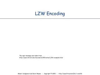
An Example Instruction Set: MIPS • This instruction set is simple yet complete • Decoding the instructions (producing control signals from the encodings) is straightforward and therefore efficient Instruction encoding
Cond 0 0 0 1 0 B 0 0 Rn Rd 0 0 0 0 1 0 0 1 Rm Cond 0 1 I P U B W L Rn Rd Offset Cond 1 0 0 P U S W L Rn Register List Cond 0 0 0 P U 1 W L Rn Rd Offset1 1 S H 1 Offset2 Cond 0 0 0 P U 0 W L Rn Rd 0 0 0 0 1 S H 1 Rm Cond 1 0 1 L Offset Cond 0 0 0 1 0 0 1 0 1 1 1 1 1 1 1 1 1 1 1 1 0 0 0 1 Rn Cond 1 1 0 P U N W L Rn CRd CPNum Offset Cond 1 1 1 0 Op1 CRn CRd CPNum Op2 0 CRm Cond 1 1 1 0 Op1 L CRn Rd CPNum Op2 1 CRm Cond 1 1 1 1 SWI Number An Example Instruction Set: ARM 31 28 27 16 15 8 7 0 Instruction type Data processing Multiply Long Multiply Swap Load/Store Byte/Word Load/Store Multiple Halfword xfer : imm offset Halfword xfer: reg offset Branch Branch Exchange Coprocessor data transfer Coprocessor data operation Coprocessor register xfer Software interrupt Cond 0 0 I Opcode S Rn Rd Operand2 Cond 0 0 0 0 0 0 A S Rd Rn Rs 1 0 0 1 Rm Cond 0 0 0 0 1 U A S RdHi RdLo Rs 1 0 0 1 Rm Instruction encoding
Summary • Today we defined a binary machine language for the instruction set from last week. • Different instructions have different operands and formats, but keeping the formats uniform will help simplify our hardware. • We also try to assign similar opcodes to “similar” instructions. • The instruction encodings and datapath are closely related. For example, our opcodes include ALU selection codes, and the number of available registers is limited by the size of each instruction. • This is just one example of how to define a machine language. • On Wednesday we’ll show how to build a control unit corresponding to our datapath and instruction set. This will complete our processor! Instruction encoding