Download
1 / 34
340 likes | 430 Vues
Explore figures depicting number representation techniques and frequency responses of quantized filters. Study transfer characteristics, noise models, and overflow operations in the context of digital signal processing. Analyze stability regions with various quantization schemes.

E N D
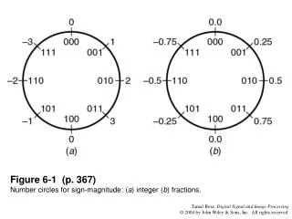
Figure 6-1 (p. 367)Number circles for sign-magnitude: (a) integer (b) fractions.
Figure 6-2 (p. 368)Transfer characteristics for quantization with sign-magnitude numbers: (a) truncation; (b) rounding
Figure 6-3 (p. 368)Number circles for two-s complement: (a) integers, (b) fractions.
Figure 6-4 (p. 369)Transfer characteristic for two’s complement truncation.
Figure 6-5 (p. 370)IEEE-754 format for floating point numbers.
Figure 6-6 (p. 373)Pole locations for a second-order Direct Form filter quantized with 4 bits.
Figure 6-7 (p. 374)Pole locations for a second-order Coupled-Form filter quantized with 4 bits.
Figure 6-8 (p. 375)Frequency response of unquantized Butterworth filter.
Figure 6-9 (p. 376)Frequency response of Direct Form filter quantized to 8 bits.
Figure 6-10 (p. 377)Frequency response of cascade-form filter quantized to 8 bits.
Figure 6-11 (p. 377)Zero locations for a linear phase FIR filter.
Figure 6-12 (p. 378) Implementation of a pair of complex conjugate poles and their reciprocals with quantization of coefficients. ^ represents coefficient quantization. This structure preserves the linear phase property.
Figure 6-13 (p. 379)Quantization noise model for a first-order filter.
Figure 6-14 (p. 380)Probability density function for noise sources: (a) sign-magnitude; (b) two’s complement truncation; (c) rounding.
Figure 6-15 (p. 382)Noise model for a second-order Direct Form II filter using a single-length accumulator.
Figure 6-18 (p. 387)Transfer characteristic of the sign-magnitude overflow operation.
Figure 6-19 (p. 387)Transfer characteristic of saturation overflow.
Figure 6-20 (p. 388)Transfer characteristic of the two’s complement overflow operation.
Figure 6-21 (p. 388)Transfer characteristic of the zeroing overflow operation.
Figure 6-22 (p. 390)Stability triangle for a second-order Direct Form filter. Shaded region: overflow stability region.
Figure 6-23 (p. 393)Stability realization of second-order filter with double pole at .
Figure 6-24 (p. 398)Quantization noise sources in a scaled second-order Direct Form II digital filter.
Figure 6-25 (p. 403)Roundoff stable region for a minimum norm filter.
Figure 6-26 (p. 404)Roundoff stable region for a Direct Form filter.
Figure 6-27 (p. 406)Stability region under magnitude truncation. (a) Coupled-Form filter, (b) Direct Form filter.
Figure 6-28 (p. 409)(a) Regions 1 and 2. Period-2 limit cycles can always be obtained. Region 3: Period-2 limit cycles may be present depending on initial conditions; Region 4: Region of global asymptotic stability; (b) Shaded region is the necessary and sufficient condition for the existence of period-1 limit cycles.
Figure 6-29 (p. 410) Stability region for a Coupled Form filter with TCQ given by sufficient condition.
Figure 6-30 (p. 411)Stability region for a Coupled Form filter with TCQ, obtained by an exhaustive search.
Figure 6-32 (p. 413)Stability region for a Coupled Form filter with TCQ implementation in a modified block form with a block size of 2.