Download
1 / 28
300 likes | 458 Vues
INWAVE: THE INFRAGRAVITY WAVE DRIVER OF THE COAWST SYSTEM. Maitane Olabarrieta & John C. Warner. COAWST WORKSHOP Woods Hole, 23 rd -27 th July. OUTLINE INTRODUCTION AND MOTIVATION IG GENERATION AND DISSIPATION MECHANISMS IG MODELLING TECHNIQUES INWAVE

E N D
INWAVE: THE INFRAGRAVITY WAVE DRIVER OF THE COAWST SYSTEM MaitaneOlabarrieta & John C. Warner • COAWST WORKSHOP • Woods Hole, 23rd -27th July
OUTLINE • INTRODUCTION AND MOTIVATION • IG GENERATION AND DISSIPATION MECHANISMS • IG MODELLING TECHNIQUES • INWAVE • a. EQUATIONS AND NUMERICAL SCHEME • b. HOW IS IT LINKED TO THE VORTEX FORCE? • c. APPLICATIONS • d. FUTURE PLANS
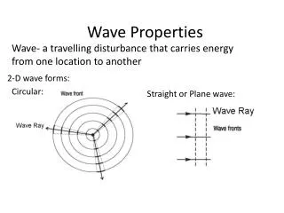
OCEAN WAVES CLASIFICATION Short Waves Long Waves 12 h 5 min 0.1 s 24 h 30 s 1 s Period Infra-gravity Waves Gravity Waves Ultra-gravity Waves Tides Capillarity Waves Long Waves Kind of Wave Storms, tsunamis Wind Sun, Moon Forcing Coriolis Surface Tension Gravity Restoring Force Energy Frequency (Cycles per second)
IG WAVE CHARACTERISTICS - They are generated by incoming wave groups. - Account for 20-60% of the offshore energy. - These long waves reflect from the shore to form cross-shore standing pattern (= minimal dissipation at shoreline). - They can propagate alongshore (edge waves), sometimes forming standing pattern. - Can significantly contribute to the surfzone circulation.
FIELD MEASUREMENTS OF IG WAVES Ruessink, 2010 ≈ 15% sea-swell infragravity Herbers et al., 1995
SOME OF THE EFFECTS OF IG WAVES BEACH MORPHOLOGY ???? RUNUP AND BEACH-DUNE EROSION HARBOR RESONANCE
MOTIVATION Under storm conditions, in dissipative beaches, the run up and swash zone dynamics are controlled mainly by the Infragravity Wave motion (Raubenheimer and Guza, 1996) Hatteras Village, North Carolina We should include these processes if we want to solve the coastal erosion, overwash and breaching Frisco, North Carolina
IG GENERATION AND DISSIPATION MECHANISM IG GENERATION MECHANISMS IN THE SURF ZONE BOUND WAVE RELEASE (Munk, 1949; Tucker, 1950) IG generation due to the breaking point movement (Symonds et al., 1984)
BOUND WAVE RELEASE (Munk, 1949; Tucker, 1950) Radiation stress gradient Pressure gradient
IG generation due to the breaking point movement (Symonds et al., 1982)
The dominance of each mechanism depends on the slope regime (Battjes, 2004)
With oblique wave incidence, free long waves can get trapped in the coast due to refraction as edge waves or be reflected offshore as leaky waves
IG DISSIPATION MECHANISM • Bottom friction. • IG wave breaking. • Energy transfer thru non-linear interactions to lower periods. It is not clear which is the main dissipation mechanism and it might depend on the beach slope and on the frequency of the IG components.
IG MODELING TECHNIQUES WAVE RESOLVING TECHNIQUES: BOUSSINESQ , PARTICLE TRACKING OR RANS MODELS WAVE AVERAGED OR PHASE AVERAGED TECHNIQUES: WAVE ACTION BALANCE EQUATION + NLSW
How do we model IG? SWAN domain: Wave spectral time scale SWAN DOMAIN DIRECTIONAL WAVE SPECTRUM Boundary region • Random phases • Double summation technique • Hilbert transform INWAVE DOMAIN BOUNDARY InWave domain: Wave group time scale Boundary condition for the wave action conservation equation Vortex Force terms varying in wave group scale FREE SURFACE ELEVATION AND WAVE ENERGY ENVELOPE TIME VARIATION Time varying Wave forcings Infragravity wave generation
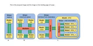
SWAN + INWAVE + ROMS COUPLING SWAN Offshore incident wave conditions (frequency- directional spectra) INWAVE Wave group energy (Hilbert transform) Bound in-coming infragravity waves (e.g. Hasselmann, 1963) Short wave (group) transformation ROMS Infragravitywave generation thru VF and propagation of the bounded IG wave Leaky, bound and trapped infragravity waves
JONSWAP, D() ~ coss() Hilbert Transform and low-pass filter Random phase model Wave group energy (Hilbert transform)
Short wave (group) transformation: INWAVE equations Wave action balance equation in curvilinear coordinate system Wave dispersion relation + Doppler relation Eikonal equation
Short wave (group) transformation: INWAVE equations Wave breaking Battjes and Janssen (1978) Roelvink (1993) H= γh
INWAVE MODEL: Incoming bound wave definition at ROMS boundaries Van Dongeren et al. (2003) -> Hasselman (1963) & Herbers et al. (1994) 1. The energy of the secondary forced elevation E3 (Df) for one particular pair of interacting primary waves can be computed following Herbers et al. (1994) 2. Bound wave out of phase with the envelope formed by each interacting pair 3. The direction of the bound wave is give by 4. The time series of the surface elevation of the bound wave is 5. This process is repeated for every pair of short-wave components. The summation of all components gives the total bound wave. Amplitude of the bound wave for each interacting pair
1D CASE APPLICATION:DUCK 85 TEST CASE (LIST 1991) R2 H1 R3 R1 VS R4 H2 H3 H4 H5 Sea surface measurements in station H5
INWAVE MODEL: INPUTS R2 H1 R3 R1 VS R4 H2 H3 H4 H5
2D CASE APPLICATION: OBLIQUE INCIDENT BICHROMATIC WAVES IN A UNIFORM BEACH slope=0.0125 (m) (m) BATHYMETRY (m)
REAL APPLICATION: HURRICANE ISABEL Time varying wave spectra
INWAVE MODEL: PRELIMINARY RESULTS SEA SURFACE ELEVATION DUE TO IG WAVES (m)
FUTURE PLANS • Validate Inwave with more test cases. • In the current configuration we need to define the wave enevelope with a netcdf file, but the idea is that the model will directly recontruct this signal from the paren t swan grid. • Inwave is not capable of including wave spectral variations along its boundaries and future efforts will be directed to include these capabilities. • Within a few months, before the end of the year Inwave will be distributed with COAWST and available for the public use.