CRT Display Technology
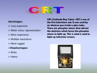
CRT Display Technology. Cathode Ray Tube Electron gun fires electrons at the screen Electric field steers the electron (X field and Y field) Screen phosphor emits light when electron hits Electron beams scans the screen, left-to-right, top-to-bottom

CRT Display Technology
E N D
Presentation Transcript
CRT Display Technology • Cathode Ray Tube • Electron gun fires electrons at the screen • Electric field steers the electron (X field and Y field) • Screen phosphor emits light when electron hits • Electron beams scans the screen, left-to-right, top-to-bottom • As the beam moves, we can set the brightness of each color • We turn on each pixel for the right about of time • We set the horizontal and vertical scan rate using SYNC signals • HSYNC - horizontal scan frequency • VSYNC - vertical scan frequency • VGA - Video Graphics Adapter • Ancient PC CRT interface standard • But still used, just like the 8086 ISA VGA Interface
VGA Timing VGA Interface
One Frame • Vertical Synch tells the monitor when to go back to the top • The Blanking Interval turns off the video at the top and bottom of the screen VGA Interface
One Line • Each frame is divided into many lines • Horizontal synch tells the monitor to go back to the start of the next line • Each line is divided into pixels • No timing signal: just change the value from one pixel to the next VGA Interface
VGA Interface • This is what the image really looks like • Horizontal retrace during HSYNC • Vertical retrace during VSYNC • “Front porch” • “Back porch” VGA Interface
Timing with a 12 MHz clock (XS40 clock) • Line: 31.77 usec x 12 MHz = 381 clocks/line • we will display 256 pixels/line • one pixel/clock • rest is front porch, back porch and HSYNC • Frame: 16.784 msec x 12 MHz = 201,406 clocks/frame (!) • 201,406 / 381 clocks/line = 528 lines • we can display 480 lines • rest is front porch, back porch and VSYNC VGA Interface
"VGA industry standard" 640x480 pixel mode • Clock frequency 25.175 MHz • Line frequency 31469 Hz • Field frequency 59.94 Hz • One line • 8 pixels front porch • 96 pixels horizontal sync • 40 pixels back porch • 8 pixels left border • 640 pixels video • 8 pixels right border • --- • 800 pixels total per line One field 2 lines front porch 2 lines vertical sync 25 lines back porch 8 lines top border 480 lines video 8 lines bottom border --- 525 lines total per field VGA Interface
VGA Interface • Row and column counts VGA Interface
VGA Interface • Simple counting will work! • HCNT • VCNT VGA Interface
VGA Interface • When HCNT is (0, 255) and VCNT is (0, 479) • Display the pixel at (x, y) = (VCNT, HCNT) • When HCNT > 255 • 313 <= HCNT <= 359 - HSYNC • When VCNT > 480 • 494 <= VCNT <= 495 - VSYNC VGA Interface
VGA Interface • Where does the pixel value come from? • The image to be displayed is stored in memory • “frame buffer” • XS40 SRAM is 32Kx8 • max image size = • 6 bits/pixel = 2 bits each of RGB (modest color) • Frame buffer model • User fills memory with image • User can change the image by just writing to memory • Monitor reads memory whenever it needs a pixel • Memory is shared, but user doesn’t need to know what monitor is doing • modularization, information hiding • VGA interface only needs to worry about reading the memory VGA Interface