Download
1 / 13
130 likes | 178 Vues
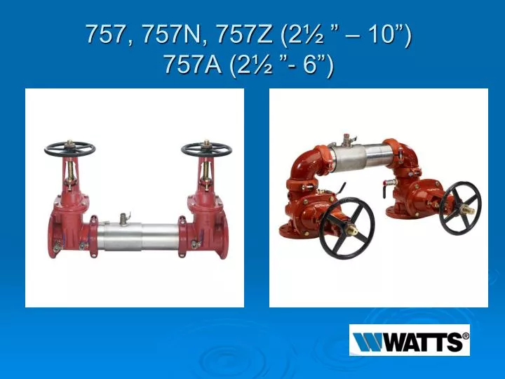
757, 757N, 757Z (2½ ” – 10”) 757A (2½ ”- 6”). Modification Overview. Production began in 2000 under the Hunter brand. In 2002 it was produced as the Watts 757 Series. (a) suffix after the model number indicates the original version that contains a bi-link check valve. Discontinued in 2008.

E N D
Modification Overview • Production began in 2000 under the Hunter brand. In 2002 it was produced as the Watts 757 Series. • (a) suffix after the model number indicates the original version that contains a bi-link check valve. Discontinued in 2008. • The current version contains a tri-link check valve. • Repair steps are the same for both check models.
Check Cover Removal 21/2”-6” • Cover slides back and is o-ring sealed. • Remove test cock # 3 from the body. • Insert a screwdriver through the hole on top of the cover sleeve. • Using both hands, rotate the cover ¼ turn clockwise and counter-clockwise to break o-ring seal.
Check Cover Removal 21/2”-6” • Slowly slide the cover sleeve to the downstream side of the housing. • Once fully pulled back, turn the sleeve 90 degrees.
Check Valve Removal 21/2”-6” • Check valve modules are o-ring sealed. • Remove the check retainer. • Remove check 1 first, then check 2. • Using a flat blade screwdriver, gently pry the module out of the body.
Check Cover Removal 8”-10” • For the 8-10” sizes, remove both Victaulic couplers. • Remove test cock # 3 from the body. • Slide the cover downstream.
Check Valve Removal 8”-10” • Modules are o-ring sealed. • Remove the 3 check retainers. • Remove check 1 first, then check 2. • Using a flat blade screwdriver, gently pry the module out of the body.
Check Seat Removal • The check seat is part of the module. • If seat is damaged, the entire module will have to be replaced.
Check Disc Replacement 21/2”-4” • The check modules are spring loaded. • Insert a screwdriver through the hole in the linkage and let it rest in the arbors on the module. • Remove the “E”-clip and pin connecting the linkage. • The clapper will open with no tension.
Check Disc Replacement 21/2”-4” • Remove the screws on the disc retainer. • Once disc is replaced, reassemble in reverse order. • Do not remove the spring assembly.
Check Disc Replacement 6”-10” • Locate the service hole on the side of the check module. • Use a ½”-13 x 5 fully threaded bolt. • Thread the bolt until the hole in the linkage is aligned with the notches in the spring arbors. • Insert a long phillips screwdriver through the hole and arbors.
Check Disc Replacement 6”-10” • Back the bolt out until the spring tension is transferred to the screwdriver. • Remove retaining clip and pin from linkage. • Spring assembly can be removed from the module. • Remove screws from disc retainer.
Check Valve Reassembly Notes • Reassemble check valves in reverse order. • Apply lubricant to o-rings. • Replace check 2 first, then check 1.