Understanding Procedures and Interrupts in Micro-Computer Applications
This document provides an overview of procedures and interrupts in micro-computer applications, discussing their significance in software architecture. It explains the concept of procedures as reusable instruction groups and details the CALL and RET instructions used for procedure linkage. The text also covers the types of procedures, NEAR and FAR, highlighting their memory handling characteristics. Additionally, it introduces macros and their structure, along with an explanation of interrupts and their relation to program control through interrupt service procedures.

Understanding Procedures and Interrupts in Micro-Computer Applications
E N D
Presentation Transcript
ELECT 707 Micro-Computer Applications: Procedures & Interrupts Dr. Eng. Amr T. Abdel-Hamid Fall 2011
PROCEDURES • A procedure is a group of instructions that usually performs one task. • subroutine, method, or function is animportant part of any system’s architecture • A procedure is a reusable section of the software stored in memory once, used asoften as necessary. • saves memory space and makes it easier to develop software
Disadvantage of procedure is time it takes the to link to, and return from it. • CALL links to the procedure; the RET (return) instruction returns from the procedure • CALL pushes the address of the instruction following the CALL (return address) on the stack. • the stack stores the return address when a procedure is called during a program • RET instruction removes an address from the stack so the program returns to the instruction following the CALL.
A procedure begins with the PROC directive and ends with the ENDP directive. • each directive appears with the procedure name • PROC is followed by the type of procedure: • NEAR or FAR • In MASM version 6.x, the NEAR or FAR type can be followed by the USES statement. • USES allows any number of registers to be automatically pushed to the stack and popped from the stack within the procedure
Procedures can be • Far – Proceduresthat are to be used by all software(global) should be written as far procedures. • Near - Procedures that are used by a given task (local) are normally defined as near procedures.
Near CALL • 3 bytes long. • the first byte contains the opcode; the secondand third bytes contain the displacement • When the near CALL executes, it first pushes the offset address of the next instruction onto the stack. • offset address of the next instruction appears in the instruction pointer (IP or EIP) • It then adds displacement from bytes 2 & 3to the IP to transfer control to the procedure.
Why save the IP or EIP on the stack? • the instruction pointer always points to thenext instruction in the program • For the CALL instruction, the contents of IP/EIP are pushed onto the stack. • program control passes to the instruction following the CALL after a procedure ends • Figure 6–6 shows the return address (IP) stored on the stack and the call to the procedure.
The effect of a near CALL on the stack and the instruction pointer.
Far CALL • 5-byte instruction contains an opcode followed by the next value for the IP and CS registers. • bytes 2 and 3 contain new contents of the IP • bytes 4 and 5 contain the new contents for CS • Far CALL places the contents of both IP and CS on the stack before jumping to the address indicated by bytes 2 through 5. • This allows far CALL to call a procedure located anywhere in the memory and return from that procedure.
RET • Removes a 16-bit number (near return) from the stack placing it in IP, or removes a 32-bit number (far return) and places it in IP & CS. • near and far return instructions in procedure’s PROC directive • automatically selects the proper return instruction • Figure 6–8 shows how the CALL instruction links to a procedure and how RET returns in the 8086–Core2 operating in the real mode.
The effect of a near return instruction on the stack and instruction pointer.
MACROS • MACRO is a symbolic name given to one or more assembly language statements. Once defined it can be invoked as many times as you wish. When you invoke a macro, a copy of macro’s statements is inserted directly into the program. It is also known as open subprogram.
Structure of a Macro • Macro_header name MACRO arguments • body of macro ……… statements to be ……… executed ……… • Macro_tail • endm
Macro to display character string • Putline macro line ; macro header • mov dx, offset line ; addr of line in dx • mov ah, 9 ; code to display line • int 21h ; interrupt for display • Endm ; macro end
Macro to read a character from a key-board Readchar macro mov ah, 1 int 21h Endm • This macro accepts one character from key-board and stores in register al.
More about macros • If macros are use in an assembly language program, they must be defined first. The macros must be defined before data segment in the program. • A macro can use (call) another macro in its body.
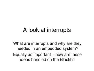
INTRO TO INTERRUPTS • An interrupt is a hardware-generated CALL • externally derived from a hardware signal • Or a software-generated CALL • internally derived from the execution of an instruction or by some other internal event • at times an internal interrupt is called an exception • Either type interrupts the program by callingan interrupt service procedure (ISP) or interrupt handler.
Interrupt Vectors • A 4-byte number stored in the first 1024 bytes of memory (00000H–003FFH) in real mode. • in protected mode, the vector table is replaced by an interrupt descriptor table that uses 8-byte descriptors to describe each of the interrupts • 256 different interrupt vectors. • each vector contains the address of an interrupt service procedure
Each vector contains a value for IP and CS that forms the address of the interrupt service procedure. • the first 2 bytes contain IP; the last 2 bytes CS • Intel reserves the first 32 interrupt vectors for the present and future products. • interrupt vectors (32–255) are available to users • Some reserved vectors are for errors that occur during the execution of software • such as the divide error interrupt
Some vectors are reserved for the coprocessor. • others occur for normal events in the system • In a personal computer, reserved vectors are used for system functions • Vectors 1–6, 7, 9, 16, and 17 function in the real mode and protected mode. • the remaining vectors function only in the protected mode
Interrupt Instructions • Three different interrupt instructions available: • INT, INTO, and INT 3 • In real mode, each fetches a vector from the vector table, and then calls the procedure stored at the location addressed by the vector. • In protected mode, each fetches an interrupt descriptor from the interrupt descriptor table. • Similar to a far CALL instruction because it places the return address (IP/EIP and CS)on the stack.
INTs • 256 different software interrupt instructions (INTs) available to the programmer. • each INT instruction has a numeric operand whose range is 0 to 255 (00H–FFH) • For example, INT 100 uses interrupt vector 100, which appears at memory address 190H–193H (400-403 decimal).
Address of the interrupt vector is determined by multiplying the interrupt type number by 4. • INT 10H instruction calls the interrupt service procedure whose address is stored beginning at memory location 40H (10H 4) in the mode • In protected mode, the interrupt descriptor is located by multiplying the type number by 8 • because each descriptor is 8 bytes long • Each INT instruction is 2 bytes long. • the first byte contains the opcode • the second byte contains the vector type number
When a software interrupt executes, it: • pushes the flags onto the stack • clears the T and I flag bits • pushes CS onto the stack • fetches the new value for CS from theinterrupt vector • pushes IP/EIP onto the stack • fetches the new value for IP/EIP fromthe vector • jumps to the new location addressed byCS and IP/EIP
INT performs as a far CALL • not only pushes CS & IP onto the stack, also pushes the flags onto the stack • The INT instruction performs the operation of a PUSHF, followed by a far CALL instruction. • Software interrupts are most commonly used to call system procedures because the address of the function need not be known. • The interrupts often control printers, video displays, and disk drives.
INT replaces a far CALL that would otherwise be used to call a system function. • INT instruction is 2 bytes long, whereas the far CALL is 5 bytes long • Each time that the INT instruction replaces a far CALL, it saves 3 bytes of memory. • This can amount to a sizable saving if INT often appears in a program, as it does for system calls.
IRET/IRETD • Used only with software or hardware interrupt service procedures. • IRET instruction will • pop stack data back into the IP • pop stack data back into CS • pop stack data back into the flag register • Accomplishes the same tasks as the POPF followed by a far RET instruction.
When IRET executes, it restores the contents of I and T from the stack. • preserves the state of these flag bits • If interrupts were enabled before an interrupt service procedure, they are automatically re-enabled by the IRET instruction. • because it restores the flag register • IRET is used in real mode and IRETD in the protected mode.
INT 3 • A special software interrupt designed to function as a breakpoint. • a 1-byte instruction, while others are 2-byte • Common to insert an INT 3 in software to interrupt or break the flow of the software. • function is called a breakpoint • breakpoints help to debug faulty software • A breakpoint occurs for any software interrupt, but because INT 3 is 1 byte long, it is easier to use for this function.
INTO • Interrupt on overflow (INTO) is a conditional software interrupt that tests overflow flag (O). • If O = 0, INTO performs no operation • if O = 1 and an INTO executes, an interruptoccurs via vector type number 4 • The INTO instruction appears in software that adds or subtracts signed binary numbers. • eith these operations, it is possible to have an overflow • JO or INTO instructions detect the overflow.
An Interrupt Service Procedure • Interrupts are usually reserved for system events. • Suppose a procedure is required to add the contents of DI, SI, BP, and BX and save the sum in AX. • as a common task, it may be worthwhile to develop the task as a software interrupt • It is also important to save all registers are changed by the procedure using USES.
Interrupt Control • Two instructions control the INTR pin. • The set interrupt flag instruction (STI) places 1 in the I flag bit. • which enables the INTR pin • The clear interrupt flag instruction (CLI) places a 0 into the I flag bit. • which disables the INTR pin • The STI instruction enables INTR and the CLI instruction disables INTR.
References: Based on slides from:B. Brey, The Intel Microprocessor: Architecture, Programming, and Interfacing, 8th Edition, 2009 & others