Download
1 / 34
350 likes | 819 Vues
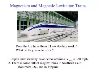
Chapter 12 Magnetism and Magnetic Circuits. 12.1 The nature of a magnetic field [page 461] Magnetism refers to the force that acts betwewen magnets and magnetic materials, e.g. iron. Magnetic field is a force field. Magnetic flux [Fig. 12-1, page 462]

E N D
Chapter 12 Magnetism and Magnetic Circuits
12.1 The nature of a magnetic field [page 461] Magnetism refers to the force that acts betwewen magnets and magnetic materials, e.g. iron. Magnetic field is a force field. Magnetic flux [Fig. 12-1, page 462] the field is strongest at the poles of the magnet. Its directionis from north (N) to south (S) external to the magnet the flux lines never cross Field patterns due to attraction or repulsion [Fig. 12-2, page 462] unlike poles attract, like poles repel
Ferromagnetic materials (p. 462) magnetic materials e.gon, nickel, cobalt. Provide an easy path for magnetic flux [Fig. 12-3, page 463] nonmagetic materials (glass, wood, plastic) have no effect on the field In Figure 12-3, magnetic field follows the path through the path through the iron. It is not affected by the plastic. Application: loudspeaker [Fig. 12-4, page 463] field is created by permanent magnet iron circuit guide the flux to air gap to provide intense field required by the voice coil
12.2 Electromagnetism (p. 464) most applications of magnetism involve magnetic effects due to electric currents. Field about a current-carrying conductor [Fig. 12-5, page 464] right-hand rule Field produced by a coil [Fig. 12-6, page 464] if the current direction is reversed, the field direction will reverse for ferromagnetic materials, almost all the flux is confined to the core [Fig. 12-7, page 465]
12.3 Flux and Flux Density (p. 465) Symbol unit Flux Weber, Wb Flux density B Teslas, T (or Wb/m2) B = / A the greater the flux density, the stronger the field [Fig. 12-8, page 465] Example 12-1 For the magnetic core of Figure 12-9 [page 465], the flux density at cross section 1 is B1 = 0.4 T. Determine B2. Solution = B1 x A1 = (0.4 T) (2 x 10⁻² m2) = 0.8 x 12-2 Wb. Since all flux is confined to the core, the flux at cross section 2 is the same as at cross section 1. Therefore, B2 = /A2 = (0.8 x 10⁻² Wb) / (1 x 10⁻² m2) = 0.8 T Figure 12-8 Concept of flux density. 1 T = 1 Wb/m2.
12.4 Magnetic Circuits (p. 467) use magentic structures to guide and shape magnetic field found in computer disk drive, tape recorder, motor, generator Recorder head [Fig. 12-10, page 467] current from amplifier pass throgh its coil, creatign a magnetic field that magnetizes the moving tape. Playback system [Fig. 12-11, page 468] voltages induced in the playback coil are amplified and applied to a speaker current from amplifier passes through flexible coil, creating a varying field that interacts with the fixed field of the speaker magnet, causing cone to vibrate
12.5 Air Gaps, Fringing, and Laminated Cores (p. 468) fringing occurs at gaps causign a decrease in flux density in gap [Fig. 12-12a, page 468] laminations [Fog. 12-12b, page 468]: effective cross-sectional area <physical area. Stacking factor: the ratio of the actual area of ferrous material to the physical area of the core.
Example 12-2 [page 469] A core swith cross-sectional dimensions of 2.5 cm by 3 cm has a 0.1-mm gap. If flux density B = 0.86 T in the iron, what is the approximate flux density in the gap? Solution = BA = (0.86 T) (2.5 x 10⁻² m) (3 x 10⁻² m) = 0.645 mWb Ag = (2.51 x 10⁻² m) (3.01 x 10⁻²,) = 7.555 x 10⁻⁴ m2 Thus, Bg = 0.645 mWb/7.555 x 10-4 m2 = 0.854 T
12.6 Series and Parallel Elements (p. 469) Series magnetic circuit [Fig. 12-13, page 469] flux is the same in all section flux density in each section depends on its effective cross-sectional area. Parallel magnetic circuit [Fig. 12-14, page 469] at each junction, sum of fluxes entering is equal to the sum of fluxes leaving.
12.7 Magnetic Circuits with DC Excitation [Page 470] Two basic problems: given the flux, to find the current required to produce it given the current, to compute the flux produced. Magnetomotive force (MMF) MMF: flux-producig ability of a coil the greater the current or the greater the number of turns, the greater will be the flux. MMF = N I (ampere-turns, At)
Reluctance, R opposition to magnetic flux. Like resistance of wire, proportional to length and inversely proportional to area. R = l / (A) (At/Wb) where = permeability - measure of how easy it is to establish flux in a material. Ohm’s Law for Magnetic Circuits = F / R Example 12-3 [page 471] For Figure 12-16, if the reluctance of the magnetic circuit is R = 12 x 104 At/Wb, what is the flux in the circuit? Solution: = N1 = (300)(0.5 A) = 150 At = / = (150 At) / (12 x 104 At/Wb) = 12.5 x 10⁻⁴ Wb
12.8 Magnetic Field Intensity and Magnetization Curves [page 471] Magnetic field intensity or magnetizing force, H -- a measure of the mmf per unit length of a circuit. mmf per unit length in [Fig. 12-17a, page 471] is more intense than [Fig. 12-17b]. H = F / l = NI / l (At/m) or H l = NI NI = mmf H I = mmf drop [Fig. 12-18, page 472]
The relationship between B and H B = H where = permeability = measure of how easy it is to establish flux in a material. increase B increase current increase H increase B increase O = 4 x 10⁻⁷
B - H curves [page 472] is not constant but varies with flux density B-H or magnetization curves [Fig. 12-19, page 473] Example 12-4 [page 473] If B = 1.4 T for sheet steel, what is H? Solution Enter Figure 12-19 on the axis at B = 1.4 T, continue across until you encounter the curve for sheet steel, then read the correspondign value for H as indicated in Figure 12-20: H = 1000 At/m. Refer to Figure 12-20 - For sheet steel, H = 1000 At/m when B = 1.4 T.
12.9 Ampere’s Circuital Law (p. 474) algebraic sum of mmfs around a closed loop in a magnetic circuit is zero Two magnetic circuit model [Fig. 12-21, page 474] This can be rewritten as F = 0 and NI = Hl
12-10 Series Magnetic Circuits: Given , Find NI (p. 465) Basic steps to solve this kind of problem : 1. Compute B for each section using B = / A. 2. Determine H for each magnetic section from the B-H curves. Use Hg = 7.96 x 10⁵ Bg for air gaps. 3. Compute NI using Ampere’s circuital law. 4. Use the computed NI to determine coil current or turns as required. (Circuits with more than one coil are handled as in Example 12-6, [page 476].) Magnetic circuit analysis is not as precise as electric circuit analysis because 1) the assumption of uniform flux density breaks down at sharp corners as you saw in Figure 12-4; 2) it is difficult to scale accurate vaklues from B-H curves, and 3) the B-H curve is a mean curve and has considerable uncertainty as discussed later (Section 12-14). Although the answers are approximate, they are adequate for most purposes.
Example 12-5 [page 476] If the core of Figure 12-24 is cast iron and = 0.1 x 10⁻³ Wb, what is the coil current? Solution Following the four steps outlined above : 1. The flux density is 2. From the B-H curve (cast iron), Figure 12-19, H = 1575 At/m. 3. Apply Ampere‘s law. There is only one coil and one core section. Length = 0.25 m. Thus, NI = Nl = 1575 x 0.25 = 393.8 At 4. Divide by N : I = 393.8/500 = 0.788 amps
EXAMPLE 12-6 [page 477] A second coil is added as shown in Figure 12-25. If = 0.1 x 10⁻³ Wb as before, but I1 = 1.5 amps, what is I2? Solution From the previous example, you know that a current of 0.788 amps in coil 1 produces = 0.1 x 10⁻³ Wb. But you already have 1.5 amps in coil 1. Thus, coil 2 must be wound in opposition so that its mmf is subtractive. Applying Ampere‘s law yields N1I1 - N2I2 = Hl. Hence, (500) (1.5A) - 200I2 = 393.8At and so I2 = 1/78 amps.
More example reluctance of air gap is high compared with that of iron mmf drop across the gap is large current flow through the coil must be increase a lot to maintain the same flux Example 12-7 [page 477] The core of Figure 12-24 has a 0.008-m gap cut as shwon in Figure 12-26. Determine how much the current must increase to maintain the original core flux. Neglect fringing. Solution Iron liron = 0.25 - 0.008 = 0.242 m. Since does not change, B and H will be the same as before. Air Gap Bg is the same as Biron. Thus, Bg = 0.5 T and Hg = 7.96 x 10⁵Bg = 3.98 x 10⁵ At/m. Ampere’s Law Nl = Hironliron + Hglg = (1575)(0.242) + (3.98 x 10⁵)(0.008) = 381 + 3184 = 3565 At. Thus, I = 3565/500 = 7.13 amps. Note that the current had to increase from 0.788 amp to 7.13 amps in order to maintai the same flux, almost a ninefold increase.
EXAMPLE 12-8 [page 478] The laminated sheet steel section of Figure 12-27 has a stacking factor of 0.9. Compute the current required to establish a flux of = 1.4 x 10⁻⁴ Wb. Solution Convert all dimensions to metric. Cast Iron liron = lab + lcdef = 2.5 + 2 + 2.5 - 0.2 = 6.8 in = 0.173 m Airon = (0.5 in) (0.8 in) = 0.4 in2 = 0.258 x 10⁻³ m2 Biron = /Airon = (1.4 x 10⁻⁴)/(0.232 x 10-3) = 0.60 T Hiron = 1850 At/m (from Figure 12-19) Sheet Steel lsteel = lfg + lgb + lha = 0.25 + 2 + 0.25 = 2.5 in = 6.35 x 10⁻² m Asteel = (0.9)(0.258 x 10⁻³) = 0.232 x 10⁻³ m2 Bsteel = /Asteel = (1.4 x 10⁻⁴)/(0.232 x 10-3) = 0.60 T Hsteel = 125 At/m (from Figure 12-19)
Example 12-8 [page 478] Air Gap lg = 0.2 in = 5.08 x 10⁻³ m Bg = Biron = 0.54 T Hg = (7.96 x 10⁵) (0.54) = 4.3 x 10⁵ At/m Ampere’s Law NI = Hironliron + Hsteellsteel + Hglg = (1850)(0.173) + (125)(6.35 x 10⁻²) + (4.3 x 10⁵)(5.08 x 10⁻³) = 320 + 7.9 + 2184 = 2512 At I = 2512/N = 2512/150 = 16.7 amps
Example 12-9 [page 479] Figure 12-28 shows a portion of a solenoid. Flux = 4 x 10⁻⁴ Wb when I = 2.5 amps. Find the number of turns on the coil. Solution Yoke Ayoke = 2.5 cm x 2.5 cm = 6.25 cm2 = 6.25 x 10⁻⁴m2 Byoke = Hyoke = 450 At/m (from Figure 12-19, page 473) Plunger Aplunger = 2.0 cm x 2.5 cm = 5.0 cm2 = 5.0 x 10⁻⁴m2 Bplunger = Hplunger = 500 At/m (from Figure 12-19)
Example 12-9 [page 479] Air Gap There are two identical gaps. For each, Bg = Byoke = 0.64 T Thus, Hg = (7.96 x 10⁵)(0.64) = 5.09 x 10⁵ At/m The results are summarized in Table 12-2. Ampere’s Law NI = Hyokelyoke + Hplungerlplunger + 2Hglg = 90 + 50 + 2(2036) = 4212 At N = 4212/2.5 = 1685 turns Table 12-2 MATERIAL SECTION LENGTH(m) A(m2) B(T) H(At/m) Hl(At) Cast steel yoke 0.2 6.25 x 10⁻⁴ 0.64 400 80 Cast steel plunger 0.1 5 x 10⁻⁴ 0.8 500 50 Air gap 0.4 x 10⁻² 6.25 x 10⁻⁴ 0.64 5.09 x 10⁵ 2036
12.11 Series-parallel magnetic circuits (p. 480) handle using the sum of fluxes principle and Ampere’s law Example 12-10 [page 480] The core of Figure 12-29 is cast steel. Determine the current to establish an air-gap flux g = 6 x 10⁻³ Wb. Neglect fringing. Solution Consider each section in turn. Air Gap Bg = g/Ag = (6 x 10⁻³)/(2 x 10-2) = 0.3 T Hg = (7.96 x 10⁵)(0.3) = 2.388 x 10⁵ At/m Sections ab and cd Bab = Bcd = Bg = 0.3 T Hab = Hcd = 250 At/m (from Figure 12-19)
Example 12-10 - Solution (cont‘d) Ampere‘s Law (Loop 2) O NI = O Hl. Since you are going opposite to flux in leg da, the corresponding term (i.e., Hdalda) will be subtractive. Also, NI = 0 for loop 2. Thus, 0 = O loop2Hl 0 = Hablab + Hglg + Hcdlcd - Hdalda = (250) (0.25) + (2.388 x 10⁵)(0.25 x 10⁻³) + (250) (0.25) - 0.2Hda = 62.5 + 59.7 + 62.5 - 0.2Hda = 184.7 - 0.2Hda Thus, 0.2Hda = 184.7 and Had = 925 At/m. From Figure 12-19, Bda = 1.12 T. 2 = BdaA = 1.12 x 0.02 = 2.24 x 10⁻² Wb 1 = 2 + 3 = 2.84 x 10⁻² Wb. Bdea = 1/A = (2.84 x 10⁻²)/0.02 = 1.42 T Hdea = 2125 At/m (from Figure 12-19, page 473) Ampere’s Law (Loop 1) NI = Hdealdea + Hadlad = (2125)(0.35) + 184.7 = 929 At I = 929/200 = 4.65 A
12.12 Series magnetic circuits: Given NI, find flux (p. 482) Example 12-11 [page 482] For the circuit of Figure 12-32, NI = 250 At. Determine . SolutionHl = NI. Thus, H = HI/l = 250/0.2 = 1250 At/m. From the B-H curve of Figure 12-19, B = 1.22 T. Therefore, = BA = 1.22 x 0.01 = 1.22 x 10⁻² Wb.
For circuit with two or more sections, the process of finding flux is not so simple. Neither flux or magnetic field intensity (i.e. H) can be found without knowing the other first. Use trial and error method. Take a guess at the value for flux, then compute NI compare the compute NI against the given NI repeat the procedure until result is within 5% error range of given NI Note that : NI = Hsteel 1steel + Hg1g As reluctance of steel << gap, assume mmf drop nearly all across the gap NI Hg1g
Example 12-12 [page 483] The core of Figure 12-33 is cast steel, NI = 1100 At, and the cross-sectional area everywhere is 0.0025 m2. Determine the flux in the core. Solution Initial Guess Assume that 90% of the mmf appears across the gap. The applied mmf is 1100 At. Ninety percent of this is 990 At. Thus, Hg 0.9NI/l = 990NI/l = 990/0.002 = 4.95 x 10⁵ At/m and Bg = OHg = 4 x 10⁻⁷) (4.95 x 10⁵) = 0.62 T. Trial 1 Since the area of the steel is the same as that of the gap, the flux density is the same, neglecting fringing. Thus, Bsteel = Bg = 0.62 T. From the B-H curve, Hsteel = 400 At/m. Now apply Ampere’s law: NI = Hsteellsteel + Hglg = (400) (0.2) + (4.95 x 10⁵)(0.002) = 80 + 990 = 1070 At This answer is 2.7% lower than the given NI of 1100 At and is therefore acceptable. Thus, = BA = 0.62 x 0.0025 = 1.55 x 10⁻³ Wb.
Example 12-13 [page 483] If the core of Figure 12-33 is cast iron instead of steel, compute . Solution Because cast iron has a larger H for a given flux density (Figure 12-19), it will have a larger Hl drop and less will appear across the gap. Assume 75% across the gap. Initial Guess Hg 0.75 NL/l = (0.75) (1100)/0.002 = 4.125 x 10⁵ At/m. Bg = OHg = (4 x 10⁻⁷)(4.125 x 10⁵) = 0.52 T. Trial 1 Biron = Bg. Thus, Biron = 0.52 T. From the B-H curve, Hiron = 1675 At/m. Ampere’s Law NI = Hironliron + Hglg = (1675)(0.2) + (4.125 x 10⁵) (0.002) = 335 + 825 = 1160 At (high by 5.45%) Trial 2 Reduce the guess by 5.45% to Biron = 0.49 T. Thus, Hiron = 1500 At/m (from the B-H curve) and Hg = 7.96 x 10⁵Bg = 3.90 x 10⁵ At/m. Ampere’s Law NI = Hironliron + Hglg = (1500)(0.2) + (3.90 x 10⁵) (0.002) = 300 + 780 = 1080 At The error is now 1.82%, which is excellent. Thus, = BA = (0.49) (2.5 x 10⁻³) = 1.23 x 10⁻³ Wb. If the error had been larger than 5%, a new trial would have been needed.
12.13 Force due to an Electromagnet [page 484] Applications of electromagnets : relays door bells lifting magnets Force created by magnetic field F = Bg2 Ag / 2O where Bg = flux density in the gap Ag = gap area
Example 12-14 [page 434] Figure 12-34 shows a typical relay. The force due to the current-carrying coil pulls the pivoted arm against spring tension to close the contacts and energize the load. If the pole face is 1/4 inch squarde and = 0.5 x 10⁻⁴ Wb,what is the pull on the armature in pounds? Solution: Convert to metric units. Ag = (0.25 in) (0.25 in) = 0.0625 in2 = 0.403 x 10⁻⁴ m2 Bg = /Ag = (0.5 x 10⁻⁴)/(0.403 x 10-4) = 1.24 T Thus, F = Bg2 Ag / 2O = 24.66 N = 5.54 lb
12.14 Properties of Magnetic Materials [page 485] magnetic properties are related to atomic structure each atom produces a tiny magnetic field for nonmagnetic materials, these fields are randomly oriented and cancel for ferromagnetic materials, the fields in small domains (Fig. 12-35, page 485), do not cancel. If domain fields line up, the material is magnetized. In Figure 12-35, random orientation of microscopic fields in a nonmagnetized ferromagnetic material is shown. The small regions are called domains.
Magnetizing a specimen [page 486] by making its domain field line up Figure 12-36 - The magnetization process. (a) Set-up (b) Progressive change in the domains as the external proportional to current I. Normal magnetization curve [Fig. 12-36, page 486] as current through coil is increased, the field strength increases and more and more domains align themselves in the direction of the field. Saturation occurs when all domain fields line up. (flat portion of B-H curve) in saturation, flux density increases slowly as magnetization intensity increases Hysteresis [page 486] after saturation, some residual magnetism retains if current reduce to zero reverse current, flux reverses form a hysteresis loop
Demagnetization process [page 486] simply turning current off does not demagnetize ferromagnetic material demagnetize by successively decreases its hysteresis loop to zero i.e. place specimen inside a coil that is driven by variable ac source and gradually decreases coil current to zero. Figure 12-38 - Demagnetization by successively shrinking hysteresis loop. 12.15 Measuring Magnetic Field [page 487] use Hall effect when a strip of semiconductormaterial is placed in a magnetic field, a small voltage, called Hall voltage appears [Fig. 12-40] for a fixed current, Hall voltage is proportional to B