Download
1 / 131
1.35k likes | 1.71k Vues
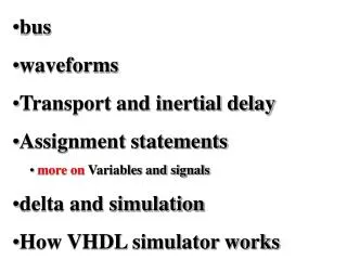
bus waveforms Transport and inertial delay Assignment statements more on Variables and signals delta and simulation How VHDL simulator works. This lecture is very important. This lecture is very important.

E N D
bus • waveforms • Transport and inertial delay • Assignment statements • more on Variables and signals • delta and simulation • How VHDL simulator works
This lecture is very important • This lecture is very important. • You can learn syntactical aspects from manual but here we discuss the principle of how the simulator works. • Therefore we will show many examples and will discuss some aspects several times from different points of view. • Please make sure that you really understand all concepts here.
Simulation Loop is based on executing signals from time queue
Some Rules for Processes These rules have to be remembered. Our next slides will explain better why it is so…
An Infinite Loop Remember: processes repeat indefinitely with new data coming. But here is not new data
A Common Error of users • It is safe to add all input signals from your circuit to the sensitivity list. You may only slow down the simulator.
A Delta-Time Infinite Loop • This is wrong way to make a clock.
Behavioral Modeling in VHDL • VHDL behavior • Sequential Statements • Concurrent Statements These are two fundamental behaviors from which all simulation and synthesis models work
VHDL behavior models: concurrent sequential
Sequential v.s. Concurrent Statements • VHDL is inherently a concurrent language • All VHDL processes execute concurrently • Concurrent signal assignment statements are actually one-line processes • Processes are re-executed if any signal in its sensitivity list is changed • VHDL statements execute sequentially within a process • Concurrent processes with sequential execution within a process offers maximum flexibility • Supports various levels of abstraction • Supports modeling of concurrent and sequential events as observed in real systems
Concurrent Statements • Basic granularity of concurrency is the process • Processes are executed concurrently • Concurrent signal assignment statements are one-line processes • Mechanism for achieving concurrency : • Processes communicate with each other via signals • Signal assignments require delay before new value is assumed • Simulation time advances when all active processes complete • Effect is concurrent processing • i.e. order in which processes are actually executed by simulator does not affect behavior • Other than in last slide Concurrent VHDL statements include : • Block, process, assert, component instantiation
Execution of parallel processes • The processes here have no sensitivity list but have wait statements
Communication Between Processes via Signals These are executed when first process allows
All these assignments executed in no time Many assignment Statements D 1 Many assignment statements Wait until D=‘1’ Wait 10nS Diagrams like this are useful to visualize time in processes and how they interact Process FIRST Process NEXT
Another example A <= 8 V=1 D 1 Wait until D=‘1’ Wait 10nS From next iteration of process NEXT D 0 V 0 Wait 10nS From first iteration of process NEXT Process NEXT Process FIRST Wait 2nS 0 2 10 D=1 A=8 V=1 -> 0 D=1 A=8 V=0 D=0 A=8 V=1 From next iteration of process NEXT
V=0 D=1 2nS A=8,V=1 10nS 10nS D=0
Signals Communicate in Between the Processes: signals propagate when processes are waiting Signals propagate within processes and between processes!
Signals Assigned After Processes Run: waiting processes can awake another processes
Example of role of WAIT in a process Assignment of value to signal C will be discussed in next slides No delay of elements Observe that there is no sensitivity list here. When A or B change, new value of variable TEMP is immediately calculated. It is used to calculate output signal C, not shown. This is just a trivial example. More will come.
Sensitivity List It is important to understand that change of c will not initiate the process here!
Process with Sensitivity List We declare arbitrary delays You can use variables to simplify description or define exact timing
Compilation and Simulation of VHDL Code • Compiler (Analyzer) – checks the VHDL source code • does it conforms with VHDL syntax and semantic rules • are references to libraries correct • Intermediate form used by a simulator or by a synthesizer • Elaboration • create ports, allocate memory storage, create interconnections, ... • establish mechanism for executing of VHDL processes compilation Internal data structures synthesis
VHDL Modeling Concepts • Semantics (meaning) of VHDL is heavily based on SIMULATION • A design is described as a set of interconnected modules • A module could be another design (component) or could be described as a sequential program (process)
VHDL Program Structure: visualization of concurrency These modules are simulated concurrently through signals This means that they are all simulated in the same time before next delta comes
A general VHDL design with modules: another visualization of concurrency Entity … is … End entity; I1 O1 I2 IO1 s1 component concurrent assignment I1 O1 architecture … of … is ... begin … end; s2 s3 s8 s9 s4 s6 process 1 process 2 concurrent assignment I2 IO1 s5 s7 This diagram helps to visualize how process communication works - concurrency
VHDL Simulator start Init t = 0 more event stop get earliest event delta delay advance time update signals This diagram helps to visualize how process communication works - concurrency execute triggered processes during process execution, new events may be added
Process Statements • FORMAT PROCESS_LABEL: process -- declarative part declares functions, procedures, types, constants, variables, etc begin -- Statement part sequential statement; sequential statement; wait statement; -- eg. Wait for 1 ms; or wait on ALARM_A; sequential statement; … wait statement; end process; Flow of control This diagram helps to visualize how process communication works - concurrency
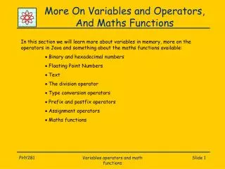
Modeling Timing in VHDL • VHDL can be used to specify different aspects of timing characteristics of hardware devices: • propagation delay of signals • operationaltime • Why we need timing? • The type “time” is a pre-defined physical type. • Mainly useful for modeling device timing characteristics • Can also be used to specify timing requirements, e.g., setup and hold times of devices. • You can parameterize timing propertiesof an entity.
EXAMPLE: Process Declaration of Clock Generator Clock_gen: process (clk) is begin if clk = ‘0’ then clk <= ‘1’ after T_pw, ‘0’ after 2*T_pw; endif; end process clock_gen; 2*T_pw T_pw
Waveform and Driver • Simulator uses drivers for signals • Adriver of a signal contains a current value and a waveform representing projected future values. • Waveform elements are appended to a driver whenever a signal assignment is executed. How to describe a waveform? Use “after”
Using Nested IFs and ELSEIFs Simulator has also to understand semantics of statements like IF Advise is to draw yourself flowchart like this to understand better
What Happens in Simulation? After examples discussed, we now understand better what are events and how they are scheduled. Details of implementation are not important at this time.
Timing Model in VHDL • VHDL uses a simulation cycle to model the stimulus and response nature of digital hardware We will introduce 3 models for delay Start Simulation Delay Execute Processes Update Signals End Simulation
Types of Delay in VHDL • All VHDL signal assignment statements prescribe an amount of time that must transpire before the signal assumes its new value • This prescribed delay can be in one of three forms: • Transport -- prescribes propagation delay only • Inertial -- prescribes minimum input pulse width and propagation delay • Delta -- the default if no delay time is explicitly specified Input Output delay
Concepts of Delays and Timing • The time dimension in the signal assignment refers to simulation time in a discrete event simulation • There is a simulation time clock • When a signal assignment is executed, the delay specified is added to current simulation time to determine when new value is applied to signal • Schedules a transaction for the signal at that time output input
More on inertial and transport models • Inertial delay • Model the time lag between stable inputs and valid output of a device • Representative of combinational logic elements • Pulses smaller than transmission delay are suppressed • Default model for VHDL descriptions • Transport delay • Model a pure delay mechanism • All pulses are transmitted • Used for transmission lines or elements with clock- cycle latency